Ah, it is a completely different story. 🙂
inspired by chief moderator Nick, series shunt regulator, Lyn Olsen came up with such idea too....😎
The simple feedback option
One can choose how much feedback is good, and there is also the option of using very simple cathode feedback.
The hint is: don't use feedback if you if you want to exploit the intrinsic advantages of pentodes.
One can choose how much feedback is good, and there is also the option of using very simple cathode feedback.
Attachments
Feedback and pentode
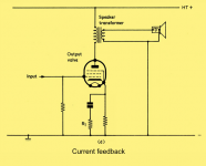
That is the method, regardless how long feedback is used. But the resistor may be placed either side of the load if the ground contact goes with it. See the drawing at the beginning of this thread.
Also a pentode looks like a natural candidate for a transconductance amplifier.
Add one more low ohm resistor between the speaker and the ground. And take feedback by current from this resistor.
That is the method, regardless how long feedback is used. But the resistor may be placed either side of the load if the ground contact goes with it. See the drawing at the beginning of this thread.
Also a pentode looks like a natural candidate for a transconductance amplifier.
Coming into the thread late but the Electrovoice amps & others did use both voltage & current FB. Voltage FB is negative, the current FB positive. Easy to do, I tried it on a small pentode PP amp before 1960. Used a short length of resistance wire to sample the current to the speaker, more later.
Seven inches of the white stuff here this AM, the Kubota tractor has already had a workout. More snow coming down now.😱
Seven inches of the white stuff here this AM, the Kubota tractor has already had a workout. More snow coming down now.😱
There is a nice hint about correct use of a pentode in the Radiotron Designer's Handbook, 4th Edition, page 563. It is pure gold.
All too true. To avoid that I design for a steeper than optimum loadline (lower P-P Impedance). The reactive speaker load will at LF resonance of the speaker drive the amplifier loadline into the knee of the plate family & further, so max power is never available for pentodes in a real World situation. While there is LF program in the signal all the other program rides on that signal. If all goes into the knee, all will be distorted.😱
We call that Intermodulation Distortion (IMD).🙂
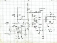
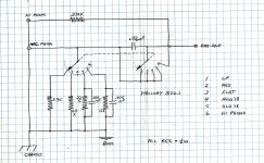
Early PP 6AQ5 Amp with Voltage & Current FB
The back page on this one tells me I built it Aug 1956. It went to a former Luftwaffe pilot I met while working at DeHavilland, an aircraft factory in Canada. He eventually became a dentist & practiced here for many years.🙂
Other than the positive current FB sensed by a short piece of resistance wire this amplifier is very ordinary. Positive current FB reduces the output impedance. The connexion to the current sense could be just as well hooked up the other way round in which case the current FB becomes negative & output impedance would increase. Or a low value resister on each side of the common with a pot across the pair & the FB can be adjusted from positive to negative. That is how Electrovoice & others did it.
Negative output impedance can be easily had which cancels some of the speaker voice coil resistance. The speaker resonant peak inverts, too much FB & the circuit becomes unstable.😱
All the iron is Hammond. The OPT is meant for a public address amplifier, only limited NFB is possible. The Hammond 1600 series today is much better.
In another experiment I tried limited NFB on the tubed amplifier in my 1953 Ford auto. The car was used when I bought it, no radio. I was interning so money was always a problem. I found a partial Ford radio in a surplus shop & finished the build. The output was a SE 6AQ5 driven by a 6AT6. So I tried NFB from the OPT secondary to the preceding grid. It measured only 0.5 db. That was on a 3R secondary, so an 8R secondary would get a little more than One db of NFB. I mention this since about the same degree of FB could be attained with a direct secondary to cathode connexion as suggested in this thread.🙂
Attachments
-
 6AQ5 PP Amplifier with Positive Curent feedback Output Stage.jpg556.6 KB · Views: 206
 -
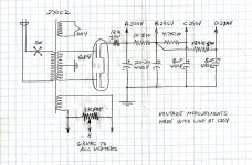 6AQ5 PP Amplifier with Positive Curent Feedback Power Supply.jpg425.1 KB · Views: 211
 -
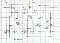 6AQ5 PP Amplifier with Positive Curent Feedback Preamp & Tone Controls.jpg586 KB · Views: 206
 -
 6AQ5 PP Amplifier with Positive Curent Feedback Input Selector.jpg469.8 KB · Views: 206
 -
 6AT6 6AQ5 SE Amplifier with Limited NFB.jpg150.2 KB · Views: 115
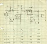
Electrovoice Amplifier with Voltage & Current FB
The DF on this amplifier is adjustable from 0.1 to 15, enough to satisfy any speaker. The speaker current enters the common connexion on the terminal block on the right hand side of the schematic. And goes to the other side of the schema to a One R current sampling resister. A voltage FB pot is tied to the current FB adjust & tracks so that instability does not result.😀How kool is that!🙂
The DF on this amplifier is adjustable from 0.1 to 15, enough to satisfy any speaker. The speaker current enters the common connexion on the terminal block on the right hand side of the schematic. And goes to the other side of the schema to a One R current sampling resister. A voltage FB pot is tied to the current FB adjust & tracks so that instability does not result.😀How kool is that!🙂
Attachments
Yeah, it is what I am doing in my amps. Additional feedback by current, via a bridge, allows me to control output impedance from negative to "current mode". All that "DF numbers" are marketing-driven, because as soon as output resistance is significantly less than DCR of the speaker, it's further decreasing does not matter. But partial compensation of the DCR does matter.
Structure of Wavebourn magic
Structure of Wavebourn magic
In Constellation-3 triode push-pull amp I took feedback by current from cathodes of output 6S19P triodes. Now I figured out how to add it to the amp with negative feedbacks to output cathodes from speaker outs...
Wavebourn,
Good points, and good amplifiers.
One more food for thought . . .
With a speaker that is not designed properly, a real high damping factor may cause the high Q crossover networks to ring . . . you do not even need the drivers to ring, the crossover networks will do the ringing for you, whether you want ringing or not.
“Those who do not know history, are not aware that we are 'in' Deja Vu.
“Those who do not know history, are not aware that we are 'in' Deja Vu.
It is even better to learn the theory in depth, and solve math problems for themselves, than pretending to be a guru while learning, opening topics inviting to discuss opinions about Ohm law implementations 😉
"Poll: What do you think about the SEP current-drive idea?"
Before answering this poll, I want to be sure about what an SEP is.
I think that Three Letter Acronyms are confusing (TLA).
When is a TLA not a Three Letter Acronym?
When it is a Thirty Letter Acronym.
Now back to the SEP . . .
Is that a Single Ended Pentode?
Just wanted to be sure.
Thanks!
Still having doubts . . .
I always thought that AMA meant American Medical Association.
Then I learned about AMA, the American Management Association.
Now, I see Slang on the internet, it says:
AMA is "Ask Me Anything" or "Against Medical Advice"
I try to write out 'Output Transformer' instead of 'OPT'.
And many other similar things, to avoid Three Letter Acronyms.
Newbies are trying to learn.
Just my opinions.
"Vote Early, and Vote Often" Deja Vu for the youngsters who were not alive then.
Last edited:
As a very nieve beginner view - in my book the tube is a current device.. only resistance gives it a change in voltage.
Sure an OTL driving a low impedance is a current drive (tongue in cheek) - typically the intermediate steps use voltage amplification due to the grids.
If you used an inverted triode, then used that to drive the grids for the next stage? An inverted-triode OTL is a simply a current drive but todo it properly the B+ needs to run through the end load.
All the 'current drive' in the pictures is doing is causing a feedback loop with additional gain needed that then causes a higher current? No real difference when using feedback to lower output impedance for driving low impedance loads.
Just beginner thoughts..
Last edited:
Single-ended indeed
Yes.
Now back to the SEP . . .
Is that a Single Ended Pentode?
Yes.
Use the 2nd harmonic distortion of a single ended pentode amplifier to partially cancel the 2nd harmonic distortion of a loudspeaker driver.
One is long on the positive alternation, and short on the negative alternation.
The other is long on the negative alternation, and short on the positive alternation.
We tried that experiment with a DPDT phase reversal switch, a single ended 2A3 DHT amplifier, and a Spica tc 50 loudspeaker.
It might be time to try it with a single ended pentode amplifier that has little or no negative feedback, and a loudspeaker.
Phase is everything if you want to try this. The DPDT might allow you to fairly easily hear the difference in tonality/timbre of the two switch settings.
2nd harmonic, vanish now
Yes. I had almost forgot but thanks for reminding. Eduardo de Lima wrote about that in his article "Why single-ended tube amplifiers?"
The essential part of his conclusion:
One may use that wisdom with any amplifier and speaker combination. What you hear is what you get, and if you don't trust your ears, then use a microphone.
Use the 2nd harmonic distortion of a single ended pentode amplifier to partially cancel the 2nd harmonic distortion of a loudspeaker driver.
One is long on the positive alternation, and short on the negative alternation.
The other is long on the negative alternation, and short on the positive alternation.
Yes. I had almost forgot but thanks for reminding. Eduardo de Lima wrote about that in his article "Why single-ended tube amplifiers?"
The essential part of his conclusion:
The really good sonic performance of a well put together system using single ended amplifiers can be understood if we consider the whole system performance. A system made using single ended amplifiers is a perfectly valid way of achieving a very good sound also from the measurements point of view. We just have to measure the correct parameter. The output of the whole system.
One may use that wisdom with any amplifier and speaker combination. What you hear is what you get, and if you don't trust your ears, then use a microphone.
I finished my new active speakers, so looking into current amplifiers again. Unfortunately I can't use LTspice that well, but will learn. In the meantime, what is your opinion about using a pentode with a "very big" resistor in the cathode and a positive bias on G1. For example, an EL84 with a 1k3 resistor in the cathode (for 52V at 40mA) and a bias of 40V on G1. The cathode resistor will further increase the output impedance, and make the pentode more linear?
ErikdeBest,
I believe you are proposing to use an un-bypassed 1k3 Ohm cathode self bias resistor.
The first thing about that, is the peak to peak drive voltage to the EL84 control grid will have to be extremely large.
The second thing is that the output transformer's primary inductance, and primary distributed capacitance will affect the frequency response to both low, and to high frequencies (even if you use an 8 Ohm resistor on the 8 Ohm tap).
And there will be an even larger frequency response effect due to the loudspeaker driver's impedance that varies widely versus frequency.
How will it sound?
That depends on the output transformer, and the loudspeaker driver.
Try it and see.
The usual gNFB circuits that take opt secondary voltage and feed it to an input stage are votlage FB amps. The Heathkit W6m had this loop, plus a series resistor to develop its current-induced voltage to feed back also. This cNFB was adjustable based on which tap/resistor combination was selected for the load.
cheers,
Douglas
cheers,
Douglas
- Home
- Amplifiers
- Tubes / Valves
- Current-drive by a valve amplifier