But . . . what is the cause of the resonance at 15Hz?
Let me guess; the floor in the living room?
Mine resonated at 11 Hz
Mechanics and electrodynamics have been assigned.
We get a voltage signal from a source and try to convert it to sound pressure. The dependency between voltage signal and sound pressure should be linear. At least we hope so.
It is the acceleration of the loudspeaker cone that causes sound pressure.
There is some mass in the cone. To have acceleration you need force.
May the force be with you, in that case you need either Star Wars or physics. Physics was chosen.
F = I L B
If L and B are constants and I is a variable, then there is a linear dependency between I and F.
Since B is constant only within a limited length of excursion, it is obvious that outside that linear range distortion will occur.
One could measure cone acceleration. Or one could measure cone velocity and derive acceleration from that. Or one could measure cone position and derive velocity from that.
Using some kind of motion feedback the linear region could be extended, but then, that limited region ends abruptly to hard limits.
When we replay music with moderate sound pressure, the voice coil will stay within the linear region.
One can imagine what the motion feedback must do when the voice coil goes out of the linear region. More juice is needed, and the voice coil will warm up.
I've often thought that current drive should be used in combination with motional feedback. To my mind it is the same principle as a current mode SMPS.
We get a voltage signal from a source and try to convert it to sound pressure. The dependency between voltage signal and sound pressure should be linear. At least we hope so.
It is the acceleration of the loudspeaker cone that causes sound pressure.
There is some mass in the cone. To have acceleration you need force.
May the force be with you, in that case you need either Star Wars or physics. Physics was chosen.
F = I L B
If L and B are constants and I is a variable, then there is a linear dependency between I and F.
Since B is constant only within a limited length of excursion, it is obvious that outside that linear range distortion will occur.
One could measure cone acceleration. Or one could measure cone velocity and derive acceleration from that. Or one could measure cone position and derive velocity from that.
Using some kind of motion feedback the linear region could be extended, but then, that limited region ends abruptly to hard limits.
When we replay music with moderate sound pressure, the voice coil will stay within the linear region.
One can imagine what the motion feedback must do when the voice coil goes out of the linear region. More juice is needed, and the voice coil will warm up.
Worst offender in driver linearity is not B but suspensions. The Cms will typically change by one order of magnitude from rest position to max linear dispacement. Unfortunately a lot of drivers do not behave linearly in this department at all. With voltage drive attempting to damp one can clearly observe a number of (unwanted) inversions on the impulse response. Such inversion are what make impulse response dirty and longer. Suspensions are generally far less linear than induction. This might be the reason why motion feedback might not be as effective as one hopes, just like feedback in amplifiers when they start clipping.....a true current amp with high internal Zout will not have this problem at least.
If I have to build a louspeaker and limit the excursion even more than the max linear excursion of its driver what's the point?
If I have to build a louspeaker and limit the excursion even more than the max linear excursion of its driver what's the point?
.Worst offender in driver linearity is not B but suspensions
One of the reasons we are starting to see drivers like the Mark Audio Alpair 5.2/3, A7ms, A11ms. Only a front suspension, no spider. The goal that Ted Jordan worked towards for so long.
dave

That's true. The hint is: don't use feedback if you if you want to exploit the intrinsic advantages of pentodes.
when driven from a high impedance source OPT design gets trickier, BW shrinks and output voltage distortion increases.
Last edited:
Very good point. Generally, good pentode output transformers need primary inductance 5-10 times that of equivalent triode stage.
Bandwidth is a lesser problem for a no- feedback stage. If you use NFB, need broader bandwidth for feedback stability.
Bandwidth is a lesser problem for a no- feedback stage. If you use NFB, need broader bandwidth for feedback stability.
With no negative feedback, and very high resistance plates . . .
The bandwidth with moderate to heavy loading on the transformer "swamps" out the effects of the primary & secondary inductance, and also the distributed capacitance of the primary.
But it makes the effect of the leakage inductance from primary to secondary,
such that the high frequencies are rolled off (unless the load impedance goes up at those high frequencies, like voice coils can do).
Lots more primary inductance requires lots more turns, and depending on how the transformer is made, can have lots of distributed capacitance.
Interleaving can split up those capacitances, and reduce the leakage inductance.
But real transformer designers know so many tricks, and the tradeoffs that they cause.
To many factors to make a generalization that fits all.
Last edited:
...It is the acceleration of the loudspeaker cone that causes sound pressure....
The cone velocity, as a fraction of the speed of sound, is the SPL as a fraction of the maximum SPL.
How do we get constant velocity?
The question is, how do we get high output resistance, "current drive", without relying on output pentode compromised by an output transformer?
Easy!
Take any amp with feedback by voltage from the secondary. Yes, it has low output resistance. Add one more low ohm resistor between the speaker and the ground. And take feedback by current from this resistor.
The problem solved.

Easy!
Take any amp with feedback by voltage from the secondary. Yes, it has low output resistance. Add one more low ohm resistor between the speaker and the ground. And take feedback by current from this resistor.
The problem solved.
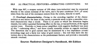
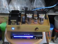
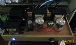
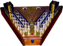
this is a 12gt5, 6bn11 all pentode single ended amp with no global negative feedback....G2 is fed by a CCS using depletion mosfet, Schade local feedback used....
Attachments

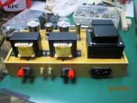
i can not complain about the sound....you should try sometime...
but i guess having a filter cap at the output of the ccs made it a gyrator yes?
but i guess having a filter cap at the output of the ccs made it a gyrator yes?
Sound pressure is proportional to the cone acceleration.
There is a fine explanation, but one sentence is essential:
You will find it here:
acoustics - Relationship between sound pressure level and amplitude of signal - Physics Stack Exchange
The cone velocity, as a fraction of the speed of sound, is the SPL as a fraction of the maximum SPL.
There is a fine explanation, but one sentence is essential:
This means that the pressure is proportional to the cone acceleration.
You will find it here:
acoustics - Relationship between sound pressure level and amplitude of signal - Physics Stack Exchange
i forgot to say, the output of the CCS is tethered with a 150 volt zener string...
Ah, it is a completely different story. 🙂
This is the amp Ultrasound once built...on request only as it was expensive.
OTL with tubes only. Zout= 200K and output peak current up to 8A. No feedback!
The other amps, more affordable, were 100% solid state or hybrid with SS output.
OTL with tubes only. Zout= 200K and output peak current up to 8A. No feedback!
The other amps, more affordable, were 100% solid state or hybrid with SS output.
Attachments
Last edited:
- Home
- Amplifiers
- Tubes / Valves
- Current-drive by a valve amplifier