... But it can not be a totem pole output, because one of the two tubes in the totem pole is cathode output, which is a relatively low impedance...
Not necessarily so,
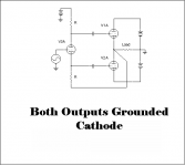
the original Futterman H1 has a bootstrap (i.e. positive FB) from output to the lower leg of a cathodyne splitter, hence both outputs run grounded cathode
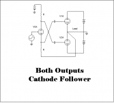
most modern totem pole OTLs use a scheme to correct this "flaw" (sometimes tagged "Inverted Futterman") which runs both outputs as cathode follower
but I agree, my notion of starting with an Atma-Shere output is also flawed because its a circlotron, so cathode follower ...
Attachments
Doesn't that make a case for OTL ?
Circlotron, no FB, something like an ATMA-Sphere 60, but with Pentodes in pentode mode, screen grids cross connected as in Electro-Voice's A50 ?
Maybe a single pair of EL509s, MOSFET driven into grid current, could do the job of three pairs of 6AS7s but with 300V supply rather than the usual 150V ...
Not many watts though but more than 20ohm output impedance and not limited by OPT reactance ...
I wondered if it’s possible to make a circlotron that included the pre stages. I modelled a circlotron, with the differential prestage criss-crossed. The issue is operating two biases with just the two floating supplies.
The m60’s output impedance means the speaker needs careful selection. It uses differential voltage feedback. Without voltage feedback it would make it more difficult.
You could do a circlotron with a output transformer, If you’re running an output transformer, I wonder if a current feedback secondary could be used on the pre current..
Last edited:


However, generally, an OTL can be quite in-efficient. Lots of power in to get a much lower percentage power out.
Like most amplifiers, there are one or more tradeoffs.
A traditional push pull amplifier with an output transformer can be modified to become a current source amplifier, and it will be much more power efficient than an OTL amplifier.
I am talking about driving 4, 8, or even 16 Ohm nominal impedance loudspeakers; with an output transformer, versus with an OTL.
I merely wanted to point out that a push pull pentode/beam power amplifier with an output transformer, by itself does not make a good current source amplifier at all frequencies.
It must have a form of feedback that is designed to overcome the output transformers low impedance secondary.
tube amps with output traffos transfer primary power to the speakers via the secondary.....
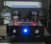
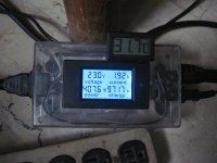
OTL amps indeed are very inefficient, my Tim Mellows OTL draws 430 watts from the 240vac power lines for an output power of merely 20 watts per channel...
Attachments
Atma Sphere markets an auto transformer with their OTLs. That has gotta tell us something!😱
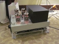
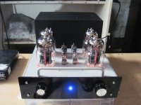
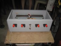
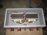
i have designed and built autotransformers for my OTL....
Attachments

TonyTecson,
Looks real nice! Transformers and case too.
I never had the desire to wind and build my own transformers.
What is the inductive reactance at bass frequencies of the autotransformer's 8 Ohm output windings?
Is it high enough to be a current source output for an 8 Ohm speaker (or at the 4 Ohm, 16 Ohm, etc. output tap?
Also, now the amplifier is no longer really an OTL.

Atma Sphere markets an auto transformer with their OTLs. That has gotta tell us something!😱
Indeed. The reality is you have three options:
1. Banks of tubes - lowing Zout and providing oodles of current
2. Autotransformer.. well let's call it what it is - an impedance matching transformer 😀
3. Throw solid state cathode followers at it or simply replace the tube final stage with a solid state output stage.
My little V1 is likely to have a switchable output stage.. either you use the heater supply (3.2A) for the circotron or for a solid state circlotron 🙂
Combining causes all sorts of phase issues if you try to keep the distinct with capacitors.
Purely speculative idea of using feedback transformers with a cyclotron. The induced current - does that count as a current feedback?

This is mostly speculation since I have not built this.
Due to less distortion, current-drive would be already widespread if the bass resonance of a conventional speaker did not spoil that. However, solving the resonance issue may bring the current-drive to markets. This probably means some kind of an aperiodic loudspeaker, and there are many possible aperiodic speaker designs. But I won't get into details. Instead of explaining reasons leading to current-drive, I concentrate in the amplifier. I started thinking, how would one design a current-drive valve amplifier.
I approach the idea with a drawing. I borrowed some graphics from W. G. Morley.
(a) A voltage feedback circuit is a good starting point. The feedback may be brought to the cathode of the output valve, a pentode in this case. Resistors R1 and R2 are there for feedback only.
(b) A pentode left without feedback is actually a kind of transconductance amplifier, but not very good one due to distortion. Otherwise it is nice and simple.
(c) A resistor is required for current feedback, so it must be series connected with the load. The amount of feedback may be adjusted by choosing the resistor.
Where is the evidence that current drive would sound better? The speakers available at present seem all built to be driven from a voltage source.
As noted, a pentode with current FB makes a good current source. Just like the 35L6s & 50L6s used in many mass produced radios of the 1940s. They sounded awful!!😱 But can be improved with voltage FB. I did several with good results. Especially driving an external speaker in a proper enclosure,🙂
Less distortion should sound better
The evidence ⸻and I don't know if this is good enough evidence for you⸻ is in the reported measurements I have seen. It has been shown in multiple independent measurements that proper current-drive leads to significantly less distortion compared to nowadays conventional voltage-drive.
Yes indeed they are. There is absolutely no doubt at all. Everyone agrees. There is a general consensus about that.
I'd like to point two common features:
Was current feedback used? I would like to see schematic drawings.
Okay, they sounded awful. I just need some details.
Where is the evidence that current drive would sound better?
The evidence ⸻and I don't know if this is good enough evidence for you⸻ is in the reported measurements I have seen. It has been shown in multiple independent measurements that proper current-drive leads to significantly less distortion compared to nowadays conventional voltage-drive.
The speakers available at present seem all built to be driven from a voltage source.
Yes indeed they are. There is absolutely no doubt at all. Everyone agrees. There is a general consensus about that.
I'd like to point two common features:
- They are usually multi-way speakers with passive crossover filters.
- Although moderate damping has been used, they are not aperiodic.
As noted, a pentode with current FB makes a good current source. Just like the 35L6s & 50L6s used in many mass produced radios of the 1940s.
Was current feedback used? I would like to see schematic drawings.
They sounded awful!!😱 But can be improved with voltage FB. I did several with good results. Especially driving an external speaker in a proper enclosure,🙂
Okay, they sounded awful. I just need some details.
Nikolas Ojala,
I like your idea of connecting the drivers in series.
Decades ago, there was a speaker company that advertised their series connected crossover.
I built a modest 2 way closed box speaker.
It used a 6 1/2" mid/woofer and a classic 'phenolic' tweeter.
The crossover was simple, a capacitor across the mid/woofer, and an air core choke across the tweeter.
('cap & mid/woofer' in series with 'choke & tweeter').
I had to pad down the tweeter slightly, I used a resistor in series with the tweeter, so the resistor in series with the tweeter had a choke across that series pair.
Sometimes, the system was placed against a wall (the mid/woofer faced up, and the tweeter faced forward).
I 'stole' that idea from a model of an Allison speaker system.
I have only used vacuum tube amplifiers, that have low to moderate damping factor to drive the series crossover speaker system.
That means I am using a resistive drive, not a voltage drive, and not a current source drive.
I was surprised, it sounded OK.
I am sure an experienced speaker system designer could have improved it.
Last edited:
Simulations look encouraging but what next?
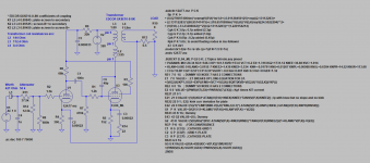
According to above mentioned idea I found an interesting schematic of a tube amplifier candidate and modified it with LTSpice. I already simulated gain, frequency response and harmonic distortion, and so far results look encouraging. I was wondering what else should I simulate?
So I guess it may be better to bring the feedback to the preceding amplifier stage. Then, I suppose, the current sense resistor may be kept small and feedback sufficient. Playing with resistance values becomes simple.
According to above mentioned idea I found an interesting schematic of a tube amplifier candidate and modified it with LTSpice. I already simulated gain, frequency response and harmonic distortion, and so far results look encouraging. I was wondering what else should I simulate?
Attachments
Originally Posted by jhstewart9 
As noted, a pentode with current FB makes a good current source. Just like the 35L6s & 50L6s used in many mass produced radios of the 1940s.
Was current feedback used? I would like to see schematic drawings.
--------------------------------------
Current FB was achieved thru the simple expedient of leaving the power tube cathode resister unbypassed.🙂
In five days this thread will be one year olde. It looks like no one is interested enough to do the work of putting such an amplifier into hardware. Then testing the results. Lots of talk & simulations.
But little real action.😀
But little real action.😀
By the way in my simulation the pentode runs too hot. By mistake I was using wrong supply voltage.
Nikolas Ojala,
I expect that there are lots of engineers that can design an excellent vacuum tube current source power amplifier.
The major problem is to have a champion for the idea to present a challenge to the Multi-Way and/or Full Range threads of diyAudio, to get them to design and build a loudspeaker that works very well when driven from a current source amplifier.
Last edited:
- Home
- Amplifiers
- Tubes / Valves
- Current-drive by a valve amplifier