This is mostly speculation since I have not built this.
Due to less distortion, current-drive would be already widespread if the bass resonance of a conventional speaker did not spoil that. However, solving the resonance issue may bring the current-drive to markets. This probably means some kind of an aperiodic loudspeaker, and there are many possible aperiodic speaker designs. But I won't get into details. Instead of explaining reasons leading to current-drive, I concentrate in the amplifier. I started thinking, how would one design a current-drive valve amplifier.
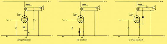
I approach the idea with a drawing. I borrowed some graphics from W. G. Morley.
(a) A voltage feedback circuit is a good starting point. The feedback may be brought to the cathode of the output valve, a pentode in this case. Resistors R1 and R2 are there for feedback only.
(b) A pentode left without feedback is actually a kind of transconductance amplifier, but not very good one due to distortion. Otherwise it is nice and simple.
(c) A resistor is required for current feedback, so it must be series connected with the load. The amount of feedback may be adjusted by choosing the resistor.
Due to less distortion, current-drive would be already widespread if the bass resonance of a conventional speaker did not spoil that. However, solving the resonance issue may bring the current-drive to markets. This probably means some kind of an aperiodic loudspeaker, and there are many possible aperiodic speaker designs. But I won't get into details. Instead of explaining reasons leading to current-drive, I concentrate in the amplifier. I started thinking, how would one design a current-drive valve amplifier.
I approach the idea with a drawing. I borrowed some graphics from W. G. Morley.
(a) A voltage feedback circuit is a good starting point. The feedback may be brought to the cathode of the output valve, a pentode in this case. Resistors R1 and R2 are there for feedback only.
(b) A pentode left without feedback is actually a kind of transconductance amplifier, but not very good one due to distortion. Otherwise it is nice and simple.
(c) A resistor is required for current feedback, so it must be series connected with the load. The amount of feedback may be adjusted by choosing the resistor.
Attachments
I've often thought that current drive should be used in combination with motional feedback. To my mind it is the same principle as a current mode SMPS.
https://www.ti.com/lit/an/snva555/snva555.pdf?ts=1604975013520&ref_url=https%253A%252F%252Fwww.google.com.au%252F
https://www.ti.com/lit/an/snva555/snva555.pdf?ts=1604975013520&ref_url=https%253A%252F%252Fwww.google.com.au%252F
Nikolas Ojala,
That is a good observation.
I believe that there were audio current sense feedback amplifiers in the 50s, if not also in the 40s. If I remember correctly, that was for controlling the woofer impedance effects and woofer mechanical resonance.
Of course, your idea is different than that.
A typical full range driver has at least one resonance in the bass, or 2 for ported, etc.
It also has a rising impedance at mid and high frequencies due to voice coil inductance.
All of these problems can be overcome with LCR Zobel networks, and other RC networks.
All of these solutions suck up power.
A typical two way loudspeaker has another resonance at the crossover from woofer to tweeter. A Zobel LCR network solves that, but sucks up power.
When a loudspeaker designer chooses a solution, in his mind might be the answer to a question: What is the customer going to use this speaker on, a solid state amp (voltage output amp), or a vacuum tube amp, or a current output amp?
Since there are so few current output amps, he might not design his loudspeaker for that.
Now, of course an experimenter, a hobbyist, or a designer, could design both loudspeaker and amplifier as a system.
I have never checked the impedance versus frequency of a Magnepan speaker, but I believe it to be quite flat, except at the crossover from woofer panel to tweeter panel.
It is low impedance, and takes lots of power. But it is probably one of the flattest impedance curves out there, and does not require Zobel network, but could use one at the crossover frequency.
There is at least one person on the Tubes / Valves threads who has amplifiers that uses Negative Resistance for better woofer performance
(again that is a system; but one that uses traditional speaker systems).
All interesting food for thought.
Perhaps there will be some more comments and enlightenment.
Last edited:
TonyTecson,
I think that Global Negative Feedback for many tube amps is often taken from the output transformer tap (the tap that goes to the loudspeaker).
The voltage is fed back to an early stage as negative feedback.
With a test generator constant sine wave, or a long flute note,
If the loudspeaker is high impedance, the voltage goes up.
If the loudspeaker is low impedance, the voltage goes down.
The global negative feedback does its best to keep the voltage constant.
That is a Voltage feedback amp.
Another way to look at it, if the loudspeaker current is great, the voltage goes down.
if the loudspeaker current is small, the voltage goes up.
The resultant voltage is fed back, resulting in a constant voltage out, to compensate for the load current.
Current-Driving of Loudspeakers
You had many good points there.
Although I skip the discussion about loudspeakers, may I recommend a book written by Esa Meriläinen: Current-Driving of Loudspeakers
At least for me that book was a source of inspiration, but you won't find valve amplifiers in that book more than a short mention.
So, if you don't mind, I will leave the discussion about speakers, also aperiodic speakers, to other threads.
Since there are so few current output amps, he might not design his loudspeaker for that.
Now, of course an experimenter, a hobbyist, or a designer, could design both loudspeaker and amplifier as a system.
You had many good points there.
Although I skip the discussion about loudspeakers, may I recommend a book written by Esa Meriläinen: Current-Driving of Loudspeakers
At least for me that book was a source of inspiration, but you won't find valve amplifiers in that book more than a short mention.
So, if you don't mind, I will leave the discussion about speakers, also aperiodic speakers, to other threads.
That seems like it may be a very good book.
I however, am not on a path for designing a current sensed negative feedback amplifier.
I bet there are threads on this forum that discuss amps that are built that way.
I have so many different models of loudspeakers, I do not even know if one single implementation of a current feedback amplifier would work with a few, or several of them.
I have enough trouble designing amplifiers that interface well with most of those loudspeakers.
Perhaps if I would design a current sensed negative feedback amplifier, it would work with most of them, but it is not a project for me now. I have too many other ideas to pursue first.
The voltage is fed back to an early stage as negative feedback.
yes, but you need to go over the VFA vs CFA thread...CFA Topology Audio Amplifiers
I notice that thread link of the VFA vs CFA is in the Solid State part of DiyAudio forum.
It might be a little harder to make a tube amp with an output transformer, that performs the same way as the last post in that Solid State thread, using 80dB of negative feedback.
It might be a little harder to make a tube amp with an output transformer, that performs the same way as the last post in that Solid State thread, using 80dB of negative feedback.
Last edited:
That is in the Solid State part of diyAudio.
One post talked about 80 dB of loop gain.
A solid state amp without an output transformer, and a vacuum tube amp with an output transformer are not the same thing.
Different design requirements, I believe.
And a tube amp without an output transformer (OTL) is different than the two above amplifiers.
For once this might be a good application for a tube OTL (pentodes). It has been done in the past by a company that unfortunately is not in the business anymore. Very expensive stuff but it worked beautifully (some 200K Zout and 8A output peak current with low distortion). No feedback, no resistor in series, no networks to compensate anything.
However, before starting CFA vs VFA one should really look into how loud speakers work and what is necessary from the drivers perspective. This is important with both topologies of course but with CFA everything becomes more critical because it relies on driver self-damping by keeping the current constant in the coil. So it can go really bad or much better. The most critical aspect of drivers is the suspension. Without good drivers with high Cs and linear behaviour ( as linear as possible although this is always far to be true, typically parabolic or worse). This means they will be expensive first thing. Without this, CFA is a waste of time and resources, IMHO. Adding a resistor in series and networks to a VFA to turn it into a CFA can be useful for an experiment but it is not a solution for best performance.
However, before starting CFA vs VFA one should really look into how loud speakers work and what is necessary from the drivers perspective. This is important with both topologies of course but with CFA everything becomes more critical because it relies on driver self-damping by keeping the current constant in the coil. So it can go really bad or much better. The most critical aspect of drivers is the suspension. Without good drivers with high Cs and linear behaviour ( as linear as possible although this is always far to be true, typically parabolic or worse). This means they will be expensive first thing. Without this, CFA is a waste of time and resources, IMHO. Adding a resistor in series and networks to a VFA to turn it into a CFA can be useful for an experiment but it is not a solution for best performance.
I notice that thread link of the VFA vs CFA is in the Solid State part of DiyAudio forum.
It might be a little harder to make a tube amp with an output transformer, that performs the same way as the last post in that Solid State thread, using 80dB of negative feedback.
the delineation between a CFA and VFA type amps are very clearly defined in those threads, and although the discussion was about solid state, the analysis can also apply to tubes....
i think that one reason tube amps with gnfb that are CFA can be traced to this...
like i said there are very few VFA tube amp types in comparison...
Leach in his papers on Low TIM said that in order to make amps that are not susceptible to TIM, open loop gains should be in the 56db or lesser gains...
and lower feedback factors.....
Last edited:
isn't majority of our tube amps current feedback types?
No.
There are no-NFB Pentode amps in kitchen radio and guitar amplifier traditions. High output impedance, OTOO 10X the nominal load.With proper choice of loudspeaker these may be "pleasing".
When we want "good" reproduction we pretty much go to "more triode-like" which means voltage feedback to get a low output impedance.
In the 1950s there were a few amps with "variable damping", from 3Xload (more current feedback) to 0.1Xload (more voltage feedback). But with mass-market loudspeakers this is always a compromise.
Nelson Pass has also written on current drive.
...CFA is the one where feedback is fed t the cathodes which is a low impedance point in comparison with the grid which i very high impedance as in VFA type....
Uh, that may be another thread. Nikolas is clearly sensing LOAD (voltage or current). It happens that his sketches show NFB to a cathode but that does not matter to the load. You were following along, I thought, when you mentioned a resistor (I thought, to sense load current).
A typical full range driver has at least one resonance in the bass, or 2 for ported, etc.
It also has a rising impedance at mid and high frequencies due to voice coil inductance.
All of these problems can be overcome with LCR Zobel networks, and other RC networks.
All of these solutions suck up power.
A typical two way loudspeaker has another resonance at the crossover from woofer to tweeter. A Zobel LCR network solves that, but sucks up power.
Power does get dissipated in those networks, but it can't be too disastrous, as all they do is to make the efficiency at resonance and in the range where the voice coil inductance comes into play as bad as the efficiency in the frequency range between resonance and the point where the voice coil inductance kicks in.
Of course the networks also mess up the current drive, as they are in parallel with the high-impedance amplifier output. I'm not sure how big a disadvantage that is for the LRC resonators, though. The argument for current drive is that the current has a rather direct relation to force while voltage is first converted into current by the not entirely linear loudspeaker impedance and is then converted to force. That makes sense far from resonance, but at resonance, the impedance is dominated by the back-EMF so the voltage has a direct relation to velocity. I could imagine that there is some finite and nonzero impedance that gives less distortion at resonance than either current or voltage drive because of a cancellation of the effect of the Bl product variations: with current drive, more Bl means more force, with voltage drive around resonance, more Bl means less velocity.
with tube pp amp with negative global feedbacks, CFA is the one where feedback is fed t the cathodes which is a low impedance point in comparison with the grid which i very high impedance as in VFA type....
The problem is that the term current feedback has at least three different meanings. In this thread it is used in its original meaning: series feedback at the output to make the output impedance high.
Off topic anecdote:
The discussion about loudspeaker efficiency and resonance reminds me of an AES article written by someone from Philips several years ago. He argued that if you wanted to get bass out of a loudspeaker with a small magnet, you could put all the low-frequency content of the music into an amplitude detector and put the detector's output into an amplitude modulator to modulate it on a carrier at the loudspeaker's resonant frequency. That would make things more efficient as loudspeakers are far more efficient at their resonant frequency than anywhere else. He also wrote that listening tests had been done and that it sounded good.
This didn't make any sense to me because the harmonic relation between the bass and the rest of the music is totally gone after such processing, until I saw that the manuscript had been received on 1st April. I then realized that it had to be an April Fool's joke that he had e-mailed to the AES on 1st April.
So I sent the author an e-mail to congratulate him with the great April Fool's joke, and got a rather annoyed reply because it wasn't a joke after all.
- Home
- Amplifiers
- Tubes / Valves
- Current-drive by a valve amplifier