I ONLY have my old DS-215-8 woofer , can't afford much more.
I am using a dome tweeter crossed over at 2K presently.
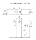
What I am curious about is the implementation of the (4th order LPF ??) and the 10R/22uf/2mH (notch filter).
The tweeter Xover is straight forward and works out in the calculators , but the 4th order is a mystery ??
MTG designs - https://www.mtg-designs.com/diy-speaker-plans/flex-8 -
has the PCB and schema to use this old woofer in what looks like a valid HQ design.
I am about to collect all the various iron core inductors and NPO caps for the woofer side of the Xover.
Is this strange implementation the "secret sauce' to tame the 1K-3K response of the LF driver ?
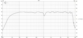
None of it works out in any online calculator but the result looks nice (below 2).
I might have better 15-20K with my properly padded dome tweeter , but I'm a little bit in awe of
this xover's complexity - would love to know how it works besides just being to identify the sections ??
PS - I'm running it now with just a 2K 2nd order on the woofer - sounds a bit bright in the vocal range.
REAL loud SPL 110+ , still a bit bright mids (but real clear) .....
I was running old (mission domes) at 1.2K - blew one of the tweeters !!
OS
I am using a dome tweeter crossed over at 2K presently.
What I am curious about is the implementation of the (4th order LPF ??) and the 10R/22uf/2mH (notch filter).
The tweeter Xover is straight forward and works out in the calculators , but the 4th order is a mystery ??
MTG designs - https://www.mtg-designs.com/diy-speaker-plans/flex-8 -
has the PCB and schema to use this old woofer in what looks like a valid HQ design.
I am about to collect all the various iron core inductors and NPO caps for the woofer side of the Xover.
Is this strange implementation the "secret sauce' to tame the 1K-3K response of the LF driver ?
None of it works out in any online calculator but the result looks nice (below 2).
I might have better 15-20K with my properly padded dome tweeter , but I'm a little bit in awe of
this xover's complexity - would love to know how it works besides just being to identify the sections ??
PS - I'm running it now with just a 2K 2nd order on the woofer - sounds a bit bright in the vocal range.
REAL loud SPL 110+ , still a bit bright mids (but real clear) .....
I was running old (mission domes) at 1.2K - blew one of the tweeters !!
OS
Attachments
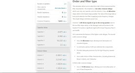
Descriptions can be deceiving. Clarity is not uncommon as a description for too much mid/treble. When it's right it doesn't sound clear, it just is clear. This is quite a different thing, and you might find it better to aim to blend adjacent parts of the spectrum so nothing stands out.
We could simulate the crossover. For now, using a generic resistive driver just to show what parts are getting the influence of the filters.
We could simulate the crossover. For now, using a generic resistive driver just to show what parts are getting the influence of the filters.
Last edited:
Here, the light blue overlay is without the RLC, showing it brings down the 700Hz region. The dark blue overlay is with the 2.2uF removed.

This region is apparently raised due to the filter itself. I'd only be guessing whether there wasn't another way. You could always try redesigning for the same response using a simpler arrangement, as a basis for moving forward.the light blue overlay is without the RLC, showing it brings down the 700Hz region.
You'll want to decide how far up to use this. 8" drivers tend to narrow near 2kHz. Also, once a driver goes into breakup, the crossover doesn't change that.Is this strange implementation the "secret sauce' to tame the 1K-3K response of the LF driver ?
Correcting breakup peaks therefore doesn't always have the expected effect. Following a 0 degree axis response can be unrealistic since it's more of an average of the wider measured curves.
https://www.daytonaudio.com/images/resources/295-430--dayton-audio-ds215-8-specifications.pdf
Edit: The factory response and impedance files are are available on their website ready to put in a simulator, notwithstanding a lack of cabinet effects.
My main question is whether to go the rest of the way and spend the 40+ dollars to complete the Xover.
MTG , I came across by buying passives on eBay , saw that he actually had done designs on many 8" PE drivers.
My box is the cut down Mission (.8cu/ft) enclosures , so the bass is quite good. Don't really matter as I have quite the sub
with a 400W hypex module. I'll be crossing over at 80hz - up for these.
OS
My understanding of the woofer crossover is still confused. Approximating with a online calc shows 1K -ish 4th order
with that big 2.5mH inductor.
MTG specifies 1.8K crossing over to his waveguide / horn.
So , it seems the woofer circuit in its complexity interacts with the impedance "quirks" of the DS-215-8 in many ways.
NOT a straight forward 4th order 1800 (below).
One of the caps come out close (16.222uF) - thats it. both inductors are smaller (1.5uH
OS
Attachments
I was running this setup with the original Mission Xover (2.25mH + 10uF). Domes were run way too low @ 1.2K
My big amps killed the tweeters with time. Totally wrong Xover , but it was the original mission one.
Since I have new domes , don't want to fry these !
Why not build it right this time.
My Polk OEM's also have a "gradeschool" B$ crossover , just 1'st order 3500hz junk.
OS
My big amps killed the tweeters with time. Totally wrong Xover , but it was the original mission one.
Since I have new domes , don't want to fry these !
Why not build it right this time.
My Polk OEM's also have a "gradeschool" B$ crossover , just 1'st order 3500hz junk.
OS
Of course. With the factory data files we could move to absolutes. Here's the response (@15 degrees) with the crossover in the first post.it seems the woofer circuit in its complexity interacts with the impedance "quirks" of the DS-215-8 in many ways.

With the expectation of baffle step, it doesn't look bad.
One thing you can't show with a single response plot though is the higher frequency performance, narrowing and breakup. It's difficult to say whether it will cross to a tweeter at this frequency.

@ostripper ,
Hello
Have you measured the drivers impedance raw in box of each driver (alone)?
I remember you are a great amp guy, have you also the gear to perform a sweep tone in room maybe for the >300 Hz as well ?
WHat happens is according the size of the box tweeter response, so original filter design doesn't work the same according the new box size. (I'm not sure if you adapted a kit in a new close box than the original kit ?)
For sibilance it is better to have recess in the 5K to 8K Hz. It changes according the listening angle too. So one thing to do (you certainly did but not said here) is to play with the toeing in and out, to chck if a part of sibilance can be tamed out.
It is a bet to buy filter parts w/o measurements : Can work (even more if Allen is leading it) but stay risky as no one is in your room at the beginning.
Should be easy and enough to follow Allen's advice, simple treble taming is maybe just what you need ! 🙂
Last edited:
Looks like MTG has it crossed to his horn @ 2K (1800). My only difference is I am using - https://www.parts-express.com/Dayton-Audio-RST28F-4-1-1-8-Reference-Series-Fabric-Dome-Tweeter-4-Ohm-275-141 .It's difficult to say whether it will cross to a tweeter at this frequency.
Using the flex 8 crossover , it seems like the horn also has a non-standard slope to match that reduced woofer output.
I'm playing with the padding of that tweeter now , 4R/20R cuts it 4db.
So cool , it fits the hole exactly. I have no wood tools.
A very "crisp" tweeter. I just don't want to blow it - make it literally "crispy" , like the last ones.
Perhaps MTG did ! looks like pretty complete measurements (with the horn). My hope is that he said the DS-215 sounded the best , even versusOf course. With the factory data files we could move to absolutes.
SEAS and matched the wool "flute woofer". It looks like he had to tweak the Xover to attain this.
Is that 2.2uF in parallel with the inductor just to fix the 1K bump in this driver's response ? Kind of advanced !
OS
MTG's box is .75cu/ft . my box is @.8 .... cut 1/3rd the 1.2cu/ft Mission box off to make smaller speakers.WHat happens is according the size of the box tweeter response, so original filter design doesn't work the same according the new box size. (I'm not sure if you adapted a kit in a new close box than the original kit ?)
I have a shorter port (2" X 7" long) , most likely tuned higher - 50+ hz.
So if "baffle step" comp. or similar is in the "special sauce" circuit , my box is similar.
The horn of the original design should not take THAT much space , maybe .1 cu/ft.
I'm not sure about phase (alignment) , my tweeter is very different.
OS
7R for the woofers. 3.5 for the tweeters.Have you measured the drivers impedance raw in box of each driver (alone)?
I'm using the padding + tweeter imp. combined to plug into the calculator.
The tweeter is where my speakers are different from the design. Box + woofer is almost identical.
OS
This shows the difference from the values in post #1..I'm playing with the padding of that tweeter now , 4R/20R cuts it 4db.
With and without..Is that 2.2uF in parallel with the inductor just to fix the 1K bump in this driver's response ?

@ostripper . Let's forget the phase. New treble high pass must be adapted from a spl curve point of view first and impedance matching. Just follow AllenB advices 👍. The measurements is a plus, but great experience knows how to aproximat like AllenB can (I can't). Those Z datas datas migth help him to help you ! 🙂.
Shortly FYI, just if you don't know (as we have the habits more to see you in the amp section) : You migth want to know the impedance of the drivers at and around the cut off chosen. Some brands make more or less precise datasheets and measurement in box can be sligthy different. SpL curve by sweep tones is helping to model the whole spl curve somation (the filter). If some big default like brigthness still exist, we know more or less how to tame them as we know where it occurs (5K to 8K). But can be tricky : can be a resonance too with its harmonics.
Shortly FYI, just if you don't know (as we have the habits more to see you in the amp section) : You migth want to know the impedance of the drivers at and around the cut off chosen. Some brands make more or less precise datasheets and measurement in box can be sligthy different. SpL curve by sweep tones is helping to model the whole spl curve somation (the filter). If some big default like brigthness still exist, we know more or less how to tame them as we know where it occurs (5K to 8K). But can be tricky : can be a resonance too with its harmonics.
Here is the predicted directivity (simplified version from factory data).
You can see that the dispersion narrows between 1-2kHz. This might have the tweeter sounding distinct where it cuts in since it widens again.
Looking at the lower plot (vertical), the crossover hits that between 2-3kHz so your ceiling may be even more distinct above 3kHz since the octave below it may be unsupported.

Wholly dependent on the accuracy of the model (which I can't verify), by playing around for just a moment I can see potential to explore.
By softening the knee of the woofer rolloff and easing the slope, I can reduce its contribution to directivity and ease the phase difference to the tweeter.
The tweeter could be benefiting from reduced lower frequency content this way.
The values chosen were partly an attempt to reuse some of the components you already have.
- Home
- Loudspeakers
- Multi-Way
- Crossover question?