EQ may be the answer to voicing concerns, but EQ can't compensate for some of the issues with the cross between the drivers.
Hope you don't mind, I did a rough sim in vituixcad going for LR4 at 2k using @DcibeL's guide for approximating baffle step. I used rough woofer Z offset of 50mm and Y offset of 178mm. Very rough guesses, but anyway, it's not as simple as Allen's, but I tracked the tweeter with a slight downward tilt as you mentioned the speakers currently sound bright. Here it is:

Attachments
Last edited:

I'm new to that website, but I agree that the woofer crossover linked is frankly weird with a brutish notch, and its almost brick wall slope does not mirror the otherwise straightforward tweeter filter at all, which is closer to LR2 than anything else, at about 2.2khz. Assuming their measurements are fine, I just started at 2k cause it's a bit removed from the glaring dip in the woofer at 1k.
But MTG was using the LaVoce DF10.101LS , at 107db.This shows the difference from the values in post #1..
In using a calculator , would I not combine the 4R with the 3.5 Re of the tweeter .... giving me 7.5R as the calc. variable ?
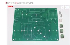
I can do that , I have lots of room on the Xover board (and the parts). This Xover (below) is so populated already - why not !Taking the tweeter to third order seems to offer more consistent phase coherence and directivity, while improving power handling.
Looks like you are only using a 2nd order filter here ? 22uF/2.5mH ? These values pan out to <1K linkwitz - riley lowpass ?By softening the knee of the woofer rolloff and easing the slope, I can reduce its contribution to directivity and ease the phase difference to the tweeter.
Looking at MTG's other designs (other 8'' drivers) - he only used the .65mH-2.2uf network (bypass , or is it a bandpass?) combo on the DS-215-8.
Must be to compensate for the 1K notch of this driver.
Man , crossovers are like "ART". Even more so than amps , modeling all these real world mechanical physics !
PS - I need to get the "L2 - L4" to populate it. I found 4mH used (unwind some to make 2.5mH) and found 2- 2mH (used).
All for about 25$. I have all the caps .... I'm the "amp guy" - I have 4 DIY amps (Wolverine,Sonance260,H-K680 ... and a HYPEX 400w) !
OS
Attachments
Last edited:
Since the impedance varies it's never better than an estimate using a calculator, and since the response isn't flat to begin with it's never quite what you want anyway.In using a calculator , would I not combine the 4R with the 3.5 Re of the tweeter .... giving me 7.5R as the calc. variable ?
Alligator clips, mic, EQ, simulator. With multiple amps, you could consider an active crossover. It won't excuse you from the design work and the filters will still be dictated by the needs of the speaker. Same primary result at the end of the day.
You need to work from measurements to be sure, measurements in the box. But it's a hard combo to work with. I tried with factory data, just for an other opinion, and came to this, assuming the drivers are on an flat front with 1cm space between them (i don't know your box).

Relative flat FR is doable, but phase alignment seems to be almost impossible. But this is on factory specs, this may or may not work in your box. To be sure, measure your box.
Relative flat FR is doable, but phase alignment seems to be almost impossible. But this is on factory specs, this may or may not work in your box. To be sure, measure your box.
Simulated baffle is that of the website (25x43cm) / Box Vb 22.5L @34Hz / CtC 15cm /XO frequency 1800Hz

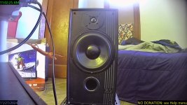
Here is the box , besides the actual dimensions - the volume is within a few liters of the "FLEX-8" spec (22L).
Port is 18+ CM long- 60mm flared.
I cut my Mission 763i's down from 35L , now they are big bookshelf speakers. The specs of the DS-215-8 worked out best with around 20L.
The bass was a bit lower <45hz in the big boxes , but now the SPL is higher across the rest of the drivers range. upper bass was "muddy" at 35L.
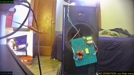
I have my 2.5 and 2mH inductors ordered , can't wait. The 1mH you see , I will reduce them to .6-.7mH.
I still have a choice on the tweeter . I did not know the tweeter needed a zoble , it's Z only deviates at it's 720hz Fs ??
I see the modeled SPL at 85-86db .... so these 3rd/4th filters order have quite some losses ? DS-215 is 90db , tweeter is 93db.
OS
Port is 18+ CM long- 60mm flared.
I cut my Mission 763i's down from 35L , now they are big bookshelf speakers. The specs of the DS-215-8 worked out best with around 20L.
The bass was a bit lower <45hz in the big boxes , but now the SPL is higher across the rest of the drivers range. upper bass was "muddy" at 35L.
I have my 2.5 and 2mH inductors ordered , can't wait. The 1mH you see , I will reduce them to .6-.7mH.
I still have a choice on the tweeter . I did not know the tweeter needed a zoble , it's Z only deviates at it's 720hz Fs ??
I see the modeled SPL at 85-86db .... so these 3rd/4th filters order have quite some losses ? DS-215 is 90db , tweeter is 93db.
OS
Attachments
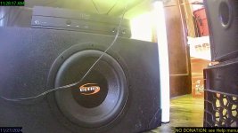
I don't have THAT many amps🙂 . I do "sub it" for music , DSP can split hard at 70-100hz. That rebuilt amp on top is class D 320W with a DIYWith multiple amps, you could consider an active crossover.
op-amp LPF (with a no B$ adjustable phase). That sub has 60mm Xmax !
I do have a full 5.1 DAC , but my top (good) DAC is just stereo (Topping E30).
Attachments
I wouldn't though. Identified problems can be worth managing but beyond that I like to use the minimum slope necessary.DSP can split hard
Nothing to do with the filter slopes. The 5/6db SPL loss is the inevitable baffle step loss from the front width of this cabinet. 85db is also similar to that MTG's final measurements.I see the modeled SPL at 85-86db .... so these 3rd/4th filters order have quite some losses ?
I have updated the simulation with your data (20L volume and the correct vent size without the flare).Here is the box , besides the actual dimensions - the volume is within a few liters of the "FLEX-8" spec (22L).
Port is 18+ CM long- 60mm flared.
I cut my Mission 763i's down from 35L , now they are big bookshelf speakers. The specs of the DS-215-8 worked out best with around 20L.
The bass was a bit lower <45hz in the big boxes , but now the SPL is higher across the rest of the drivers range. upper bass was "muddy" at 35L.
I have my 2.5 and 2mH inductors ordered , can't wait. The 1mH you see , I will reduce them to .6-.7mH.
I still have a choice on the tweeter . I did not know the tweeter needed a zoble , it's Z only deviates at it's 720hz Fs ??
I see the modeled SPL at 85-86db .... so these 3rd/4th filters order have quite some losses ? DS-215 is 90db , tweeter is 93db.
OS
SPL is 85 dB because of the baffle step loss.
I used a notch on the TW because there is too much energy in the 2-3kHz range given from the tw response summed to the woofer breakup. I tried to reduce that energy and get a better in-room and power responses, but then the on-axis response sucks because the blanket is always short when you cross an 8" to a tw over.
XO is LR4 acoustic @ 1750Hz
I attached the files I used if you wanna play in VCad.
Attachments
Last edited:
In my project attached earlier, the tweeter CR tilts down the high-end response, which otherwise continues to rise with its impedance from 2-20khz.I did not know the tweeter needed a zoble
Noob , what's that ?the tweeter CR
So "viruixcad" is a speaker sim ?
How faithful are the driver models , or does it create them from raw T/S specs ?
At least I know something (from my amp work).
OS
vituixcad is more of a crossover simulator.
Crossover means a few things.. the electrical network, the physical configuration and the acoustic design that comes before it. Vituixcad helps with the first two. The third is taken into account when you create a measurement set. While you'd normally measure, Vituixcad can simulate aspects such as boxes, inside and out which can be helpful when baffle step information isn't available.
You can supply the T/S information, box simulation is fairly mature. This isn't always within the crossover range and I often work without simming rear enclosures as long as the levels can be established.
Tweeter Cap+Resistor shunt.what's that ?
Vituixcad, yes a speaker simulation tool.So "viruixcad" is a speaker sim
You will find a thread about it on diyAudio with several postings by the author of the software.
You feed the tool with impedance and (if possible polar 360° horizontal and vertical) frequency response data, ideally measured in the actual enclosure.
You then simulate (and optimize) the crossover network and driver positions and get very accurate resulting on-axis frequency response, polar response, power response, in-room-response, directivity index, etc., in short: a good estimation how the speaker will behave in an actual listening situation.
What I would like to do is plug in the post #1 Xover to see what MTG's "flex -8" design does by itself.
Even as I thank all for these tips , I might just go with the original design. I have the PCB and BOM.
All I might have to do is reverse engineer for the domes I have....
Speaker parts are freakin' expensive , hard to re-purpose inductors and big poly caps.
I have extra 6.8uF xover caps - use them for "audiophile" amp input caps. "Wolverine" PCB's have pads for
35mm caps.
NPO electros are still rather cheap , room (and $$) to play around.
OS
- Home
- Loudspeakers
- Multi-Way
- Crossover question?