Wow, 4 more pages since yesterday. This thread has been moving fast.
As Douglas remarked, I'm also not sure how much info is too much or if the OP wants to just concentrate on the xo simulation aspect for now. I just think it's better to have some design parameters to start off with.
So besides looking at how driver directivity and Fs influence xo choices, the other 2 things I mentioned were harmonic distortion and cone resonances. I couldn't find both of these for all the drivers but I've attached below what I did find.
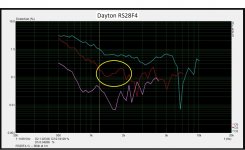
Let's start with the tweeter.
1 - 3rd order in red is the worst offender and doesn't start to increase until below about 1200Hz. That means a low xo point is in the cards. (image from www.audioexcite.com)
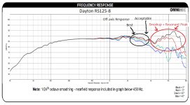
2 - A repeat in visuals of the mid's FR noting best and acceptable off-axis range and the bad stuff from cone break-up and resonance peak. It may actually be hard to hear but that 12000Hz peak should be well down in the mix.
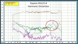
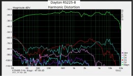
3 - Harmonic distortion for the mid though shows some peaks at about 2600Hz and 4000Hz. Also something you want to keep down suggesting it's best crossed over below about 2000Hz. (image from ZaphAudio)
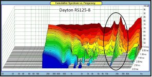
4 - Cumulative Spectral Decay for the mid just reinforces what that 12kHz resonance peak looks like. (also from Zaph)
5 - Looking at the woofer now, harmonic distortion is excellent between about 40Hz and 1000Hz. No real limitations here. (can't actually remember where I copied this graph from but it was only HD not the CSD)
Conclusion? The tweeter is capable of a lower xo point and the mid is probably best with one too. I would probably try out LR2 acoustical at 300-400Hz for the lower xo point and maybe LR4 acoustical at about 2000-2300Hz.
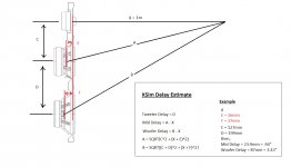
Pic 6 is how I estimate the delay variable for the mid and woofer in XSim. Basically I imitate the mic set-up I would use to actually physically measure the drivers for the purpose of obtaining the delay. Note that we are trying to determine the differences in path lengths from the listening/mic position to the acoustic centers of the drivers. In both PCD and VCAD you only have to input the mic/listening distance and driver positioning and the program will do the geometry for you. Here in XSim, you need to take the extra step and do the calculations yourself.
To figure out the acoustic center distances, I use the spec sheet for the drivers blown up to real size on my screen and then physically measure with a ruler. Acoustic center for a normal tweeter is at about the bottom of the faceplate. The AC for the other drivers is best determined where the cone meets the voice coil or right about where the spider is. Acoustic centers in the pic are what I came up with using this method. That makes the delay data good to go into the program.
As Douglas remarked, I'm also not sure how much info is too much or if the OP wants to just concentrate on the xo simulation aspect for now. I just think it's better to have some design parameters to start off with.
So besides looking at how driver directivity and Fs influence xo choices, the other 2 things I mentioned were harmonic distortion and cone resonances. I couldn't find both of these for all the drivers but I've attached below what I did find.
Let's start with the tweeter.
1 - 3rd order in red is the worst offender and doesn't start to increase until below about 1200Hz. That means a low xo point is in the cards. (image from www.audioexcite.com)
2 - A repeat in visuals of the mid's FR noting best and acceptable off-axis range and the bad stuff from cone break-up and resonance peak. It may actually be hard to hear but that 12000Hz peak should be well down in the mix.
3 - Harmonic distortion for the mid though shows some peaks at about 2600Hz and 4000Hz. Also something you want to keep down suggesting it's best crossed over below about 2000Hz. (image from ZaphAudio)
4 - Cumulative Spectral Decay for the mid just reinforces what that 12kHz resonance peak looks like. (also from Zaph)
5 - Looking at the woofer now, harmonic distortion is excellent between about 40Hz and 1000Hz. No real limitations here. (can't actually remember where I copied this graph from but it was only HD not the CSD)
Conclusion? The tweeter is capable of a lower xo point and the mid is probably best with one too. I would probably try out LR2 acoustical at 300-400Hz for the lower xo point and maybe LR4 acoustical at about 2000-2300Hz.
Pic 6 is how I estimate the delay variable for the mid and woofer in XSim. Basically I imitate the mic set-up I would use to actually physically measure the drivers for the purpose of obtaining the delay. Note that we are trying to determine the differences in path lengths from the listening/mic position to the acoustic centers of the drivers. In both PCD and VCAD you only have to input the mic/listening distance and driver positioning and the program will do the geometry for you. Here in XSim, you need to take the extra step and do the calculations yourself.
To figure out the acoustic center distances, I use the spec sheet for the drivers blown up to real size on my screen and then physically measure with a ruler. Acoustic center for a normal tweeter is at about the bottom of the faceplate. The AC for the other drivers is best determined where the cone meets the voice coil or right about where the spider is. Acoustic centers in the pic are what I came up with using this method. That makes the delay data good to go into the program.
Attachments

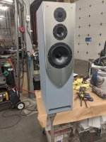
Lots of good info there! I'm hoping to have the drivers in the cabinet yet this afternoon so I can start breaking them in. I'll post some actual dimensions for the driver locations later this evening.
Just so you know ... Something has come up and I'm going to be rather busy for a couple of days ... I might be a bit slow getting back to you.
I'm giving my thoughts on the upper xo a bit of a re-think. That harmonic distortion on the mid isn't too too bad and it isn't accompanied with corresponding resonances, so I'm thinking LR2 slopes at between 2k and 3kHz should roll it off adequately. Maybe only consider LR4 if that doesn't work out in the sims or it doesn't sound good.
I'm a bit slow on all the edits... but I think the RS225-8 will only have a net ssystem sensitivity of ~ 86dB after 3dB bafflestep - or lower if you aren't intending a sub or putting these in a large room away from the front wall.
Therefore check the sims at a 2.83v level and make sure they have sufficient BSC.
Get this wrong.. and it usually has a ripple effect changing most components in the deisgn.
Therefore check the sims at a 2.83v level and make sure they have sufficient BSC.
Get this wrong.. and it usually has a ripple effect changing most components in the deisgn.
Is the woofer delay math correct here? I get 26.1mm for your example. My C is 127mm and my D is 191.5mm so my woofer delay is 26.02 or 1.024" if my math is correct.
Attachments
Last edited:
I took a guess on your driver spacing and came pretty close.
As far as I can figure it out, yes I think my math is correct. I loaded the formula into Excel and I've triple checked it and triple checked it again. I get the same mid delay of 23.9mm and now I get a woofer delay of 84.8mm.
Just checked it again with a lowly calculator. Same result.
As far as I can figure it out, yes I think my math is correct. I loaded the formula into Excel and I've triple checked it and triple checked it again. I get the same mid delay of 23.9mm and now I get a woofer delay of 84.8mm.
Just checked it again with a lowly calculator. Same result.
The other thing too jwilhelm is to ensure the woofer and midrange responses also have the vertical off axis rolloff applied - or you will end up being too agressive in the acoustic slope in your crossover.
Thats why getting good source data - with rolloff, bafflestep and diffraction applied is very important BEFORE xo simulation
Thats why getting good source data - with rolloff, bafflestep and diffraction applied is very important BEFORE xo simulation
The Edge is good at accounting for microphone offset to the driver axis so account for the rolloff.
I'd also recommend modeling the enclosure rolloff for midranges. if you are going t low Q sealed enclosures (e.g. QTC 0.5) then you might find the rolloff occurs as high as 300Hz and this will lessen the response below, and therefore your HP on the midrange crossing to the woofer could also be too agressive, causing a upper bass / lower Mid broad dip.
I'd also recommend modeling the enclosure rolloff for midranges. if you are going t low Q sealed enclosures (e.g. QTC 0.5) then you might find the rolloff occurs as high as 300Hz and this will lessen the response below, and therefore your HP on the midrange crossing to the woofer could also be too agressive, causing a upper bass / lower Mid broad dip.
The other thing too jwilhelm is to ensure the woofer and midrange responses also have the vertical off axis rolloff applied - or you will end up being too agressive in the acoustic slope in your crossover.
Thats why getting good source data - with rolloff, bafflestep and diffraction applied is very important BEFORE xo simulation
I'm going to get some proper measurements once the drivers are broken in. Hopefully I can get them run in this weekend. In the meantime I'm just trying to figure out how to work the software correctly.
The Edge is good at accounting for microphone offset to the driver axis so account for the rolloff.
I'd also recommend modeling the enclosure rolloff for midranges. if you are going t low Q sealed enclosures (e.g. QTC 0.5) then you might find the rolloff occurs as high as 300Hz and this will lessen the response below, and therefore your HP on the midrange crossing to the woofer could also be too agressive, causing a upper bass / lower Mid broad dip.
The Q for the mid enclosure is .707. If I remember correctly it rolled off around 100Hz (I did the modeling for it on another PC, don't have the files here)
The other thing too jwilhelm is to ensure the woofer and midrange responses also have the vertical off axis rolloff applied - or you will end up being too agressive in the acoustic slope in your crossover.
This is interesting. I haven't seen anybody recommend using anything other than the on-axis responses for simulation purposes. PCD includes a function to change the listening axis to look at the power response once you get a xo worked up. That can be quite informative. Unfortunately that's something XSim lacks. So sometimes I'll sim in both programs if the topography of the xo isn't too complex for some of the limitations in PCD.
Can you explain a little more?
Actually I just figured out what you mean as I re-read the post.
The Diffraction and Boundary Simulator allows you to make horizontal and vertical adjustments as well. It's an interesting point if going for the utmost accuracy.
The Diffraction and Boundary Simulator allows you to make horizontal and vertical adjustments as well. It's an interesting point if going for the utmost accuracy.
Very few of us actually listen at 45 degrees off axis so if you extend the criteria to -6dB you can get a wider spread for the midrange; which may or may not be of benefit.
Moondog55, I've been busy today so I almost let this one slip by.
That rule of thumb isn't about listening off-axis, it's about power response and room reflections. We primarily hear the on-axis response but our perception is also colored by room reflections. So if there is a small range in the FR before the tweeter response where the mid's off-axis response is weaker, we will perceive that as an overall dip in the FR in the listening position despite the fact that the on-axis FR might measure flat.
So if you can keep the FR as omni-directional as possible all the way up to where the tweeter finally starts to get directional, you will have a better sounding speaker.
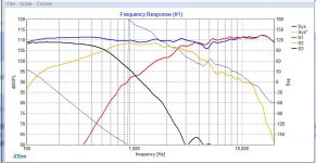
I finally got the driver delay math to work out properly and entered it into Doug's crossover design. The resolution of my display (large icons on a TV) won't let me see the OK button when I try to display the driver phase so I can't see it but I assume that's what's causing the drop in response between 3 - 10k.
Attachments
- Home
- Loudspeakers
- Multi-Way
- Crossover Critique