jwilhelm,
I'm not sure what your exact goals are here so I'm wondering what the next best step is for you.
The feeling I get is that you are most interested in working with XSim and then measuring and finalizing a real xo. Now that you've worked a bit with some semi-accurate files the next thing to do would be to work with simmed files that have been correctly constructed, so including box and baffle effects.
Maybe you want to learn how to do this now or maybe later would be fine. It looks to me like you are a busy man. In which case, I can work the files up for you and post a new version of XSim for you to go to work on. It'll be instructive to see the difference in the xo values between the 2 versions of files. Or I can help you work up the files yourself if you want that.
If you want me to work things up for you, I'll need to know front baffle dimensions and the distance from the top of the cabinet to the middle of the tweeter. Also if the side round-over is 1/2" or other.
@Dave Bullet,
I gave the vertical off-axis effects a little more thought and looked at it in both the Diffraction and Boundary Simulator (DBS) and the Edge.
I think why I didn't worry about this back when I was learning the software is because DBS shows virtually no difference in the response when looking from off the main axis. Now that I know a little bit more than I did back then, that actually surprises me. The response does change but it shows no roll-off at the upper most frequencies at all!!
The Edge on the other hand shows a whole heck of a lot. So much so that I had to actually make a comparison with the real off-axis measurements of some random woofer and the Edge's sims were not even close. They showed way too much roll-off. When I changed the mic distance to about twice as far away, then they started to resemble the driver's off-axis measurements. So not very accurate in my opinion. And of course there is still the problem with the Edge of no edge radius included.
That leaves VituixCAD which I haven't got around to trying yet but which does look like it operates like the Edge but also includes radius effects. I may have to try it soon.
I take your meaning though on the roll-off effects in the sims but as they are at the very end of the tail and because they increase the roll-off and not the other way around I don't see the effects as too, too important. But once I get up to speed with VCAD, I think I want to look at it again more closely.
As this is kind of off topic for the thread, if you want to discuss it further, I'll open up a new one.
I've been wondering about baffle and box effects. It seems kind of counter-intuitive working with infinite baffle driver responses and trying to figure out how to tame a driver that's in a box, especially the woofer. How is this normally done? Does the driver response files simply get replaced with responses in the cabinet?
I definitely want to learn the whole process of designing a crossover, but you're obviously light years ahead of me in the learning curve, so if you could put together something that would be awesome! Any learning material or pointers to how you came up the design would be appreciated as well.
I definitely want to learn the whole process of designing a crossover, but you're obviously light years ahead of me in the learning curve, so if you could put together something that would be awesome! Any learning material or pointers to how you came up the design would be appreciated as well.

This is interesting. I haven't seen anybody recommend using anything other than the on-axis responses for simulation purposes. PCD includes a function to change the listening axis to look at the power response once you get a xo worked up. That can be quite informative. Unfortunately that's something XSim lacks. So sometimes I'll sim in both programs if the topography of the xo isn't too complex for some of the limitations in PCD.
Can you explain a little more?
Yes sure. Obviously the rolloff is an off axis function. As I understand it power response deals normally deals with the horizontal? Happy to be corrected here.
As per the attached, the vertical rolloff is just a function of the off-axis vertical angle, the piston diameter and measuring distance. Obviously an increase in off-axis, piston diameter an/or decrease in measuring distance will amplify the effect.
Whether or not the rolloff is in your passband.. depends. I might be overcompensating, overthinking... but I like to get as much "data" into my simulations as possible.
Like you - I try and use different tools to converge on the same result. As you note, some tools have some features others lack, so a few might be needed to get a complete picture.
Attachments

@Dave Bullet,
I gave the vertical off-axis effects a little more thought and looked at it in both the Diffraction and Boundary Simulator (DBS) and the Edge.
I think why I didn't worry about this back when I was learning the software is because DBS shows virtually no difference in the response when looking from off the main axis. Now that I know a little bit more than I did back then, that actually surprises me. The response does change but it shows no roll-off at the upper most frequencies at all!!
The Edge on the other hand shows a whole heck of a lot. So much so that I had to actually make a comparison with the real off-axis measurements of some random woofer and the Edge's sims were not even close. They showed way too much roll-off. When I changed the mic distance to about twice as far away, then they started to resemble the driver's off-axis measurements. So not very accurate in my opinion. And of course there is still the problem with the Edge of no edge radius included.
That leaves VituixCAD which I haven't got around to trying yet but which does look like it operates like the Edge but also includes radius effects. I may have to try it soon.
I take your meaning though on the roll-off effects in the sims but as they are at the very end of the tail and because they increase the roll-off and not the other way around I don't see the effects as too, too important. But once I get up to speed with VCAD, I think I want to look at it again more closely.
As this is kind of off topic for the thread, if you want to discuss it further, I'll open up a new one.
Sorry missed your post. That is interesting. I have also switched to VCAD. It's very good and I am a novice. There's a lot to discover and master.
Yes agreed - we are taking off topic. Sorry OP.
Hey Jeff. Great progress! Looking forward to watching this.
@jReave... since we're dealing with a 3 way, it could be tricky to measure the woofer so that floor bounce (which I estimate ~478Hz based on: Floor/Ceiling Reflection Calculator and assuming a tweeter listening axis and simulated 2.5m listening distance) is not included in the crossover sims. That's the advice of people like Zaph (JKrutke). He recommends a groundplane measurement to avoid making the pitfall of factoring the floor bounce dip into the crossover. he noted that in his SB12.3 writeup.
I don't know if I quite agree / understand him. What I normally do is:
a) measure nearfield
b) measure farfield
c) simulate the baffle diffraction of the woofer
Use Jeff Bagby's FRD response blender... which splices the above, applying baffle diffraction and step effect to the nearfield response, so you don't get an artificial boost at low frequencies... you can also choose your merge point, so should be able to splice above the floor bounce dip to avoid in the crossover sim.
Anyway, I'd be interested in your thoughts.
Right then. I'll try to keep this short. 😛
I actually use Unibox to do my box sims because I like how it works but I essentially use Response Modeler for all the work needed to put the new frd and zma files together.
Here's my process:
FRD FILES
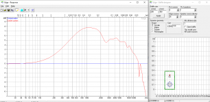
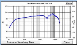
- import the Dayton raw FR (infinite baffle). Pic 1
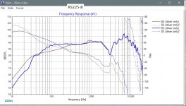
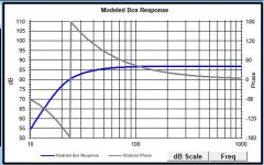
- model box effects. Pic 2 - the vented box alignment is 45L tuned to 24Hz (it's ok here if this isn't exactly what you used) and then splice it to the raw FR
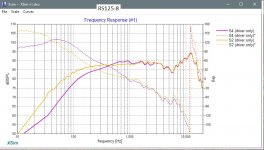
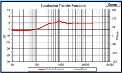
- model baffle diffraction effects - pic 3. This time I included the vertical off-axis effects. 7.4 degrees for the mid. 18.5 degrees for the woofer at 1 m distance.
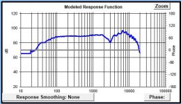
- then add the above to the Dayton frd files. Pic 4
- repeat for the mid.
- just add the baffle diffraction effects to the tweeter because it is closed back so there are no new box effects.
IMPEDANCE FILES
- for the zma files, again no new box for the tweeter so nothing changes.
- for the mid and woofer, the bottom part of the impedance is changed due to the effects of putting it into a box but the upper part will still be the same. It's kind of analogous to what happens to the FR - the LF's are altered but the HF's stay the same. For the FR, you splice the 2 responses together but for the impedances, you reshape the simulated curve to match the original in the upper frequencies. The simulation pretty much never gets the upper part completely right so this is a necessary step.
And that's it. We've already taken care of the XSim delays so the last thing to do is to extract minimum phase when importing the files into the program which was covered in my 1st post.
I will often do the process twice to make sure that I have done everything right. Here I double checked against the files you attached in your 1st post and I was confounded by the tweeter. I double and triple checked the original frd files and compared against Dayton's spec sheet FR graph and the conclusion I reached is that you imported a different tweeter file into your original program. You'll probably have some insight into this now that you think about it. I hope.
Pics 5, 6 and 7 are comparisons between your original FR's and my files with baffle diffraction and box effects added in.
Also attached is Douglas's 1st XSim try but now with all the new files. You'll also see 3 other drivers over on the left of the schematic window. These are target filters to help you shape the responses to start off with. I chose LR2 for each xo point at 350Hz and 2300Hz. These are not set in stone but are a good way to help you get the curves into the shape that you want them. I found them very, very helpful when I was starting out. In the FR graph under 'Curves' choose '(driver only)' for these targets. I'm following what Rich did in another thread now and putting them all in grey. Start with the woofer and set the amp to a level that puts the target filters at about the 100-200Hz level of that driver. I found about 3W to be about right and have set it that way to start. Then work your way up to the mid and then the tweeter.
And..... lastly, just a suggestion. The last pic is how I'm setting up XSim on my screen these days to help me keep track of all the variables at the same time.
Have fun. 😉
I actually use Unibox to do my box sims because I like how it works but I essentially use Response Modeler for all the work needed to put the new frd and zma files together.
Here's my process:
FRD FILES
- import the Dayton raw FR (infinite baffle). Pic 1
- model box effects. Pic 2 - the vented box alignment is 45L tuned to 24Hz (it's ok here if this isn't exactly what you used) and then splice it to the raw FR
- model baffle diffraction effects - pic 3. This time I included the vertical off-axis effects. 7.4 degrees for the mid. 18.5 degrees for the woofer at 1 m distance.
- then add the above to the Dayton frd files. Pic 4
- repeat for the mid.
- just add the baffle diffraction effects to the tweeter because it is closed back so there are no new box effects.
IMPEDANCE FILES
- for the zma files, again no new box for the tweeter so nothing changes.
- for the mid and woofer, the bottom part of the impedance is changed due to the effects of putting it into a box but the upper part will still be the same. It's kind of analogous to what happens to the FR - the LF's are altered but the HF's stay the same. For the FR, you splice the 2 responses together but for the impedances, you reshape the simulated curve to match the original in the upper frequencies. The simulation pretty much never gets the upper part completely right so this is a necessary step.
And that's it. We've already taken care of the XSim delays so the last thing to do is to extract minimum phase when importing the files into the program which was covered in my 1st post.
I will often do the process twice to make sure that I have done everything right. Here I double checked against the files you attached in your 1st post and I was confounded by the tweeter. I double and triple checked the original frd files and compared against Dayton's spec sheet FR graph and the conclusion I reached is that you imported a different tweeter file into your original program. You'll probably have some insight into this now that you think about it. I hope.
Pics 5, 6 and 7 are comparisons between your original FR's and my files with baffle diffraction and box effects added in.
Also attached is Douglas's 1st XSim try but now with all the new files. You'll also see 3 other drivers over on the left of the schematic window. These are target filters to help you shape the responses to start off with. I chose LR2 for each xo point at 350Hz and 2300Hz. These are not set in stone but are a good way to help you get the curves into the shape that you want them. I found them very, very helpful when I was starting out. In the FR graph under 'Curves' choose '(driver only)' for these targets. I'm following what Rich did in another thread now and putting them all in grey. Start with the woofer and set the amp to a level that puts the target filters at about the 100-200Hz level of that driver. I found about 3W to be about right and have set it that way to start. Then work your way up to the mid and then the tweeter.
And..... lastly, just a suggestion. The last pic is how I'm setting up XSim on my screen these days to help me keep track of all the variables at the same time.
Have fun. 😉
Attachments
-
XSim v1 w modified files.dxo131.9 KB · Views: 48
-
 XSim screenshot.JPG417 KB · Views: 72
 -
 RS225-8 new old.jpg175.3 KB · Views: 71
 -
 RS125-8 new old.jpg169.3 KB · Views: 63
 -
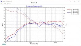 RS28-4 new old.jpg157.7 KB · Views: 157
 -
 RS225 FR + VB + BD.JPG45.9 KB · Views: 151
 -
 wfr BD.JPG46.4 KB · Views: 149
 -
 RS225 VB.JPG50 KB · Views: 161
 -
 RS225 raw FR.JPG44 KB · Views: 173
@jReave,
I found the target curves extremely helpful. Response Modeler is an excellent program.😀 That is a cool feature to be able to create and export .frd files like that to use in Xsim. I was even able to figure it out myself without to much thinking (after you explained it to me). Your work flow is spot on and very organized! Sorry I have not been much assistance on this project. Golf course activity has taken off and I have been in catchup mode.
Best Regards,
Rich
I missed these replies, no notifications from the forum last night for some odd reason. I have been using Unibox for years for sub-woofer box designs. I like that software! I was wondering if the FRD files produced by it would be of value here? I used WinISD to model this design because everyone told me it's much better, but I think it came out with pretty much the same numbers so I don't really see a lot of advantage.
How did you make the "target" drivers?
In my office I have multiple monitors so it's easy to view everything. Here at home I use a big screen TV that works out great for CAD design, but sucks pretty badly with all crossover software! The need to run large icons causes all kinds of issues with things not being displayed.
Last edited:
@jwilhelm,
Concerning the which is better debate between Unibox vs. Winisd, I like using them both in tandem. There is very good features with each. You may know this already but if not, you can modify Ql, Qa, and Qp parameters in Winisd to match Unibox under the advanced tab when you click on box. If not you might not get agreement between the two programs.
With regards to creating target drivers, jReave can explain much better than myself but I will take a stab.😀 If you have Response Modeler installed, you can look down the left hand column and find high pass/ low pass rows. From there all you need to do is select desired Fc and desired textbook response that is highlighted in blue. Than click on load load coefficient values tab and your created target curve will appear in the upper modeled response function screen. Than to finish just click save modified result to FRD tab. Then name your created frd file and save to project folder. Repeat this process for the remaining target curves. Once all have have been generated, you can access them in Xsim by adding speakers that are not connected to your schematic as jReave has done in the latest .dxo file. The last step is to click tune and select FRD response file then load your created target curve. Hopefully I was clear enough explaining this process. If not, we may need to enlist jReave's assistance.😀
Best Regards,
Rich
I think I can figure it out from your instructions. Thanks!
I'll be elbows deep in Bondo and primer on the second cabinet for the day but I hope to get back at the software later today.
I see Doug is on vacation for a bit. That sucks! I like having his "voice of reason" when figuring things out.
I'll be elbows deep in Bondo and primer on the second cabinet for the day but I hope to get back at the software later today.
I see Doug is on vacation for a bit. That sucks! I like having his "voice of reason" when figuring things out.
@jwilhelm,
Have fun with your project today.😀 I need to head off to work and continue my irrigation add-on project on the golf course where I am employed. I rather be working on my own project that is in the final stages.
Best,
Rich
Have fun with your project today.😀 I need to head off to work and continue my irrigation add-on project on the golf course where I am employed. I rather be working on my own project that is in the final stages.
Best,
Rich
Sorry I have not been much assistance on this project. Golf course activity has taken off and I have been in catchup mode.
No worries at all Rich. Very glad that you can actually keep working right now.
@jwilhelm,
Box equations should be the same in Unibox or WinISD so if you feed them the same data the results should be the about the same. I haven't touched WinISD now in a couple of years so I'm not clear on all its features, but just something like the "Save Graph" tab in Unibox adds a lot of value for me. I also just much prefer the Unibox interface. For some reason, I just don't find the way WinISD functions to be intuitive. And bonus, Unibox is still working perfectly for me in Windows10 and with a newer Office suite whereas some other older Excel programs not so much.
Thanks Rich for the target curve explanation. One other point - if you enable both the HP and LP filters at the same time, you'll get the target curve for a mid in a 3-way. Also what I did is just took a 1/2 hour one day and created a 'Filter' file. Then I created a slew of target filters, I left them all at the default 90dB and then just saved them all to the new file. Now they are always right there when I need them.
Another little advantage to Unibox is you can import these filters into the sims as well in the 'Frequency Response Correction Filter' window. It's a good way to look at the cone excursion/power relationship if you are using a HP filter on a driver, like a mid in a 3-way or a woofer with a sub. You'll usually see that the driver is no longer limited by xmax but by its max power rating instead.
@jReave,
I knew you would have more tricks up your sleeve.😀 I just learned some new features of Unibox. Excellent stuff!
Have a great day,
Rich
I knew you would have more tricks up your sleeve.😀 I just learned some new features of Unibox. Excellent stuff!
Have a great day,
Rich
Hey Jeff. Great progress! Looking forward to watching this.
@jReave... since we're dealing with a 3 way, it could be tricky to measure the woofer so that floor bounce (which I estimate ~478Hz based on: Floor/Ceiling Reflection Calculator and assuming a tweeter listening axis and simulated 2.5m listening distance) is not included in the crossover sims. That's the advice of people like Zaph (JKrutke). He recommends a groundplane measurement to avoid making the pitfall of factoring the floor bounce dip into the crossover. he noted that in his SB12.3 writeup.
I don't know if I quite agree / understand him. What I normally do is:
a) measure nearfield
b) measure farfield
c) simulate the baffle diffraction of the woofer
Use Jeff Bagby's FRD response blender... which splices the above, applying baffle diffraction and step effect to the nearfield response, so you don't get an artificial boost at low frequencies... you can also choose your merge point, so should be able to splice above the floor bounce dip to avoid in the crossover sim.
Anyway, I'd be interested in your thoughts.
Lots of confusion here for people who haven't understood the method of quasi-anachoic measurement that Jeff Bagby has explained so well in this paper, Box, which I'm going to guess you have read. Just a hunch. 😀
First let's look at floor bounce. Since we're talking about its effect on measurements, we should use those data points in the floor bounce sims. Using your link, I used driver height of 22", mic height of 34.5" and a mic distance of 1m. I get the 1st null at 250Hz. Using Jeff's Diffraction and Boundary Simulator I get the same result, attached below.
Now if we measure the woofer nearfield which will not include the floor bounce effects, its upper end of accuracy will be 4311/7", 7" being the RS225-8's cone diameter. That will be 615Hz. The accuracy of the low end of our farfield measurement of the same driver will be determined by the gating time we choose, where the lower limit is defined by 1/gating time. With a 5ms gate, that will be 200Hz.
So as long as we blend the 2 measurements together between about 300Hz (the top end of the floor bounce null) and 615Hz, the floor null will not be present in the blended response. Problem solved. There is no need to take the speakers outside to measure nor do you need to raise the speaker up off the floor either.
Attachments
- Home
- Loudspeakers
- Multi-Way
- Crossover Critique