Arite,
I pulled each component for the gate drivers and they checked good.
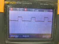
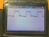
Attached is the drive signal on pins 9 and 10 of the 494. (Pins lifted).
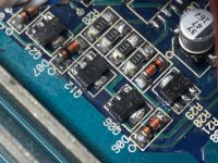
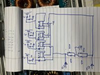
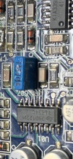
I’ve also taken a close up of the components and drew a quick sketch to try to figure out why this is not working. Seems this is not the traditional EF pair.
I pulled each component for the gate drivers and they checked good.
Attached is the drive signal on pins 9 and 10 of the 494. (Pins lifted).
I’ve also taken a close up of the components and drew a quick sketch to try to figure out why this is not working. Seems this is not the traditional EF pair.
Attachments
The diodes will be 1N4148/1ss355 types (SMD versions). Don't replace them unless you have to.
For the transistors, I'd likely use a 2SB1260.
Without the voltage on all of those terminals, I'm working blind.
For the transistors, I'd likely use a 2SB1260.
Without the voltage on all of those terminals, I'm working blind.
494:
1. 0.002
2. 5.019
3. 0.110
4. 3.260
5. 1.167
6. 3.669
7. 0.002
8. 11.30
9. 0.128
10. 0.129
11. 11.29
12. 11.30
13. 5.018
14. 5.018
15. 5.018
16. 0.002
1. 0.002
2. 5.019
3. 0.110
4. 3.260
5. 1.167
6. 3.669
7. 0.002
8. 11.30
9. 0.128
10. 0.129
11. 11.29
12. 11.30
13. 5.018
14. 5.018
15. 5.018
16. 0.002
Terminal 4 is very high. Also, it appears that there is some signal on terminals 9 and 10. Set the scope to 5v/div and 10uS and re-check.
Last edited:
Adjust the 12v supply voltage. Does the rail voltage vary?
Find what's driving terminal 4 of the 494 high.
Find what's driving terminal 4 of the 494 high.
Last edited:
I have the power supply set to 13v.
When the amp powers up the voltage drops to 11.8 (7 amps) and the rail voltage is 39.90v.
When I increase the voltage the rails increase to 43.22v and don’t go further.
When the amp powers up the voltage drops to 11.8 (7 amps) and the rail voltage is 39.90v.
When I increase the voltage the rails increase to 43.22v and don’t go further.
You’re correct, trace went under a cap.... its connected to several caps, and transistors on the 5v line....I have to shut down for today, I’ll trace it around and report back what I find.
Find the transistor that's connected between terminals 14 and 4, that should prevent terminal 4 from being pulled up.
This may disable the protection circuit so be careful when you power up.
This may disable the protection circuit so be careful when you power up.
I checked, and this transistor has pin 4 ( via a 4.7 ohm resistor) on the collector and Pin 14 on the emitter.
I pulled this transistor and powered up, it pulled the voltage on the power supply down to 7v and the amps went up to 13.4a.
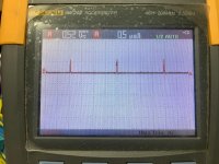
I had the scope across the gate on the PS FETs.
I pulled this transistor and powered up, it pulled the voltage on the power supply down to 7v and the amps went up to 13.4a.
I had the scope across the gate on the PS FETs.
Attachments
I didn’t try Audio. After a minute or so when I saw the current draw was up to 13a and the colts dropped to 6v I shut off.
The current has to be passing through some of the components. It's hard to believe that nothing is getting hot.
- Home
- General Interest
- Car Audio
- Crossfire vr4000d