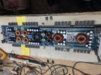
Arite, I removed the board from the heatsink and powered up without audio.
The amplifier pulled the power supply down again to 7v and the amps went up to 13a.
All PS FETs and output FETs are getting warm. I didn’t keep it powered for long though.
The amplifier pulled the power supply down again to 7v and the amps went up to 13a.
All PS FETs and output FETs are getting warm. I didn’t keep it powered for long though.
Have you checked all of the rectifiers and output FETs?
You may have to pull the rectifiers to determine if the problem is in the audio or in the power supply section.
You may have to pull the rectifiers to determine if the problem is in the audio or in the power supply section.
All FETs tested ok, I already tested the rectifiers, but didn’t think to power up with them out the circuit, I read somewhere in the manual, class D may not like this.
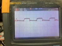
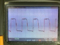
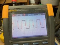
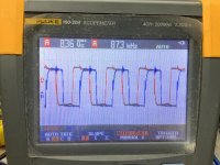
Anyways I removed the Rectifiers and powered up. Attached is a pic of the gate drive. ( I still have the transistor removed)
I have 40v ac on either side of the board where the two sets of rectifiers were.
Anyways I removed the Rectifiers and powered up. Attached is a pic of the gate drive. ( I still have the transistor removed)
I have 40v ac on either side of the board where the two sets of rectifiers were.
Attachments
You can't fully troubleshoot with no rail voltage for some class D amps. Unless I'm forgetting something, I can't remember it being harmful in any way.
If the problem is in the audio circuit and no semiconductors are heating up, you may have a defective rail cap.
If the problem is in the audio circuit and no semiconductors are heating up, you may have a defective rail cap.
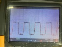
The first waveform is the gate drive on the PS.
The second on the p-FETs,
The third on the n-FETs.
All 18 caps removed and checked, several were just over half their capacity.
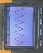
Amp returned to heatsink and tested with a 45hz sine wave.
Tested ok, onto ordering parts....
Thanks a mil perry!
The second on the p-FETs,
The third on the n-FETs.
All 18 caps removed and checked, several were just over half their capacity.
Amp returned to heatsink and tested with a 45hz sine wave.
Tested ok, onto ordering parts....
Thanks a mil perry!
Attachments
I got in all caps for the secondary on the power supply and installed. powered up amplifier and amp cycles on and off/ in and out of protect (red and blue led).
I removed the caps and amp does the same. then reinstalled them.
All FETs tested ok (none were replaced or burnt).
With the amp in protect I've measured the following, the double values are the ones that are changing as the amp cycles on and off:
494:
1. 0.002
2. 4.933
3. 0.056
4. 4.25 / 2.91
5. 1.46
6. 3.62
7. 0.002
8. 11.96
9. 0.062
10. 0.026
11. 11.93
12. 11.93
13. 4.933
14. 4.933
15. 4.933
16. 0.002
393:
1. 0.114
2. 3.69 / 0.21
3. 11.85
4. 5.80 / 5.28
5. 4.725
6. 4.725
7. 3.51 / 3.05
8. 4.425
9. 2.33
10. 0.002
11. 0.002
12. 0.002
13. 0.002
14. 0.114
I removed the transistor (connected across pins 4 and the 5v line of the 494) as was done earlier, amp comes out of protect but draws around 13a current and pulls the power supply voltage down to 7.5v. Rail voltage goes up to 40vdc.
As before, all the heatsink mounted components are beginning to get warm and I remove power.
I've retested all resistors and transistors in and around the 494 and 339 and they've tested good thus far.
I removed the caps and tried earlier (without caps) and the amp cycled in and out of protect, i then reinstalled with the same result.
I matched their current orientation vs pics I took prior to removal earlier this month and the PCB is marked for the negative side. all caps are installed correctly.
I matched their current orientation vs pics I took prior to removal earlier this month and the PCB is marked for the negative side. all caps are installed correctly.
I have two series connected caps in place of the bipolar.
I removed these first when I got the cycling problem, but they didn't seem to contribute to it.
I removed these first when I got the cycling problem, but they didn't seem to contribute to it.
I removed all caps as were previously installed.
Amp cycles in and out of protect.
Seems there’s something driving pin 4 of the 339 high and pin 4 of the 494 high. I get the dc voltages as previously posted.
Will have to continue tracing around.
Amp cycles in and out of protect.
Seems there’s something driving pin 4 of the 339 high and pin 4 of the 494 high. I get the dc voltages as previously posted.
Will have to continue tracing around.
Look for a solder bridge, either near the pads of the components you soldered or for a drop of solder that could have fallen on the board.
After a lengthy detailed look at the soldering, caps in and out, it seems the main rail caps (1500uf 100v) are the culprits sending the amp into protect. They were not part of the initial troubleshooting last month and I didn't order replacements.
They're testing fine out the amp and show no physical signs of damage.
For now I've installed all other caps and amp powers up fine and passes clean audio.
Thanks for the patience and assistance Perry.
They're testing fine out the amp and show no physical signs of damage.
For now I've installed all other caps and amp powers up fine and passes clean audio.
Thanks for the patience and assistance Perry.
I did a bit more this afternoon as time permitted, I installed one cap at a time and powered up.
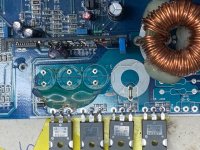
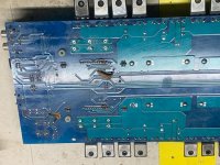
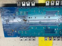
I noticed the amp goes into protect when I install a cap or a group of caps on the negative rail that connects to the N- channel FETs.
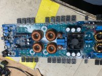
I wired in external rail caps and wires to these caps as the double sided circuit board has opposing voltages from top to bottom, and I wanted to eliminate this from the troubleshooting (solder bridges).
Presently the amp powers up fine with all caps (replacement caps wired externally) except for these two banks of caps on the N-FETs. I've tried various caps, new, old, varied the value a bit, but the amp seems not to like these in.
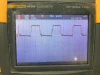
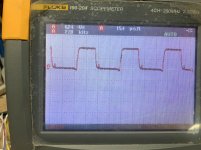
I traced the PCB, the negative voltage rail, connects directly to the source of the N-FET and the negative of the cap. The positive of the cap connects to the common on the power supply (common point between the rail caps).
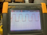
I've attached a couple of pics of the gate waveforms for both banks of N-FETs, when the amp is up and running without these N-FET caps, and both sides of the PCB.
Anyone ever experienced this and/or has an explanation for this?
I noticed the amp goes into protect when I install a cap or a group of caps on the negative rail that connects to the N- channel FETs.
I wired in external rail caps and wires to these caps as the double sided circuit board has opposing voltages from top to bottom, and I wanted to eliminate this from the troubleshooting (solder bridges).
Presently the amp powers up fine with all caps (replacement caps wired externally) except for these two banks of caps on the N-FETs. I've tried various caps, new, old, varied the value a bit, but the amp seems not to like these in.
I traced the PCB, the negative voltage rail, connects directly to the source of the N-FET and the negative of the cap. The positive of the cap connects to the common on the power supply (common point between the rail caps).
I've attached a couple of pics of the gate waveforms for both banks of N-FETs, when the amp is up and running without these N-FET caps, and both sides of the PCB.
Anyone ever experienced this and/or has an explanation for this?
Attachments

I remember a similar problem that I had with an amp using driver boards similar to these.
When the rail caps were not fully charged, the amp would draw excessive current and would not start.
Do both driver boards start to produce drive signals immediately? Is either delayed?
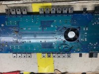
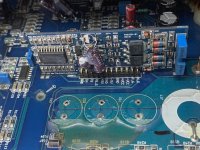
Post a photo of the pin designations on the top of the main board for the driver board.
When the rail caps were not fully charged, the amp would draw excessive current and would not start.
Do both driver boards start to produce drive signals immediately? Is either delayed?
Post a photo of the pin designations on the top of the main board for the driver board.
I would say both driver boards start at the same time, my scope takes a second or two to lock onto the signal.
The amp when remote applied, does the protect led for one second and then switches over to power on (I believe this to be normal for an amp this size).
The amp when remote applied, does the protect led for one second and then switches over to power on (I believe this to be normal for an amp this size).
Attachments
You don't have to wait for the scope to lock onto the signal. Set it to 2ms and simply notice when the signal on the output filter caps (input side) goes from a straight line to a rail-rail signal.
- Home
- General Interest
- Car Audio
- Crossfire vr4000d