I then removed the screws from the upper FET on both channels at that side of the boards (rear of amp, 50 ohm gate stopper side). Did not remove the devices. Sorry, I didn't read the devices to see if they are the N or P channel.
I verified that the D was no longer connected to the rail on the PCB. Shorting the G-S and measuring S-D:
Good channel: 3.06M with the + lead on the S and the - lead on the D (case of device). Open when I reverse the leads.
Bad channel: 3.32M + on S, - on D. Open when I reverse the leads.
So, from this test, it appears that the FET is good (or at least I can't tell if it is bad in the bad channel).
There is an awful truth hidden here. You are testing a power device with a low voltage low current tester (DMM). This will let you know about shorts and opens but no more. Power devices have multiple bond wires between the die and the package. You need all of them for correct operation but a power device will test ''OK' with just one bond wire still attached for the drain and source. So all this investigation is delaying the point where you apply full rail voltage and check for smoke.
The DMM checks will tell you only if it is a complete waste of time to do a full voltage test.
And you need to do this on all the MOSFETs on the dodgy side. You can remove the two screws from a MOSFET and do a test and then replace the screws, one MOSFET at a time so the whole assembly does not fall apart. The p-channel devices are at the front and the n-channel devices are at the back.
S on either channel is connected directly to the amp output for that channel. Still getting 27K on good channel S->GND, and 2.6M on bad channel S->GND. So something other than the devices is causing this. Since I don't have the schematic, I have no idea what else it could be? Any suggestions as to how to proceed? Should I check all of the devices on the bad channel? If the DC resistance at the amp output is supposed to be ~27K, then I don't see how a bad FET could cause it to increase into the M ohm range.
At first glance that puzzles me too, so I'll have a ponder and get back to you. In the meantime, see if you can test each individual MOSFET (bad side only) as suggested above.
Revisiting an earlier discussion point, and back pedaling ever so slightly, I recommend you arrange a Variac for the final test. Assuming that we determine that you are safe to proceed to that step.
Hi Chris,
I'll dig out the diagram. We don't normally use resistance measurements beyond open, short or some low resistances. The diode check is more common when looking at semiconductors. What I normally do is run the variac up a bit while watching the current draw. At some low voltage points, I stop and measure DC offsets, power supply values, bias currents (1R0 resistor in the fuse location, I use 0R1 so I can run it also). In this case, gate potentials are what I watch first unless the current draw begins to rise. It's all about where the current is going, and should any current be flowing to begin with. Very yes - no kinds of questions that help you troubleshoot.
With the relay pulled, the resistance reading should be high and ill-defined (who knows what the exact value should be?). There is a 10 K resistor that leads to a current source and zener diode used to stabilize the bias circuit.
Between the two sets of gates, there is a zener diode network. The diodes you were going to replace. Can you use the diode check function on your DVM to make sure you get a high diode voltage drop (0.7x volts as opposed to 0.5x to 0.6x volts) in the forward conduction direction, and open in reverse. This will find any odd faults that would not show up until later when you power it up. While you're at it, check the junctions on the bias transistor (Q1) mounted on the heat sink. Also check the diodes across the output mosfets for shorts. You should not see a low resistance to ground from the sources. That should be next to open unless you have some kind of load connected.
-Chris
Edit: Hi Alan,
You posted as I was digging out the diagram (and looking for component values). I agree with you on your advice but went back to basics a bit more.
Last edited:
Still getting 27K on good channel S->GND, and 2.6M on bad channel S->GND. So something other than the devices is causing this.
Got it. There is a 27.91k resistor network from output to ground which is part of the APC voltage sensing circuit. On the good side these parts are OK and so you are measuring that resistance, with maybe a bit of stray leakage in parallel. Or your DMM is cheap 😀
Take a look a the top left hand corner of your burnt up APC board. To the left of the charred remains of VR1 and VR2 you will see a bit of carbon that used to be part of this resistor chain.
Conclusion: the high impedance measurement from source to ground on the bad side does not indicate anything untoward.
If you really wanted to confirm this you could disconnect R1 on the good APC board and see if you get ~ 2.6M on the good side (source to gnd, again). R1 is located just to the left of VR1. It is mounted vertically on the board so you could snip the lead and make it an open circuit for the test.
Hi Alan,
Glad you found the path. My information doesn't show a connection, even though it must be there. I generally don't go through the analog computer at all.
I haven't examined this circuit Alan, but have you ever seen one burnt like this? I haven't yet.
-Chris
Glad you found the path. My information doesn't show a connection, even though it must be there. I generally don't go through the analog computer at all.
I haven't examined this circuit Alan, but have you ever seen one burnt like this? I haven't yet.
-Chris
I have not seen this level of destruction in the APC before. Reviewing the implicit design history, the RevA board that we are looking at, has a flaw in the power supply for the APC board that was fixed on the revB boards. It seems ironic that the APC board in this amp could be as much a cause as a remedy for reliability issues.I haven't examined this circuit Alan, but have you ever seen one burnt like this? I haven't yet.
-Chris
If we can get the bad channel running, then I think due consideration needs to be given to preventing the APC board on the good side from going bad in the future. Either by upgrading it or by disconnecting it as we have done on the faulty side.
I like these amps, but they sure do take a lot of effort when things go bad.
Hi Alan,
Since that circuit has no practical purpose to be running, I would think that disconnecting it would be the safer option.
I have people begging me to redesign these amps similar to what they've heard with the SA-100 changes. There is a person that was going to give me a dead chassis for this purpose (with the power transformer). It hasn't appeared yet.
-Chris
Hi Chris,
At some low voltage points, I stop and measure DC offsets, power supply values, bias currents (1R0 resistor in the fuse location, I use 0R1 so I can run it also). In this case, gate potentials are what I watch first unless the current draw begins to rise. It's all about where the current is going, and should any current be flowing to begin with. Very yes - no kinds of questions that help you troubleshoot.
<snip>
Can you use the diode check function on your DVM to make sure you get a high diode voltage drop (0.7x volts as opposed to 0.5x to 0.6x volts) in the forward conduction direction, and open in reverse. This will find any odd faults that would not show up until later when you power it up. While you're at it, check the junctions on the bias transistor (Q1) mounted on the heat sink. Also check the diodes across the output mosfets for shorts. You should not see a low resistance to ground from the sources. That should be next to open unless you have some kind of load connected.
-Chris
I'll check these. I had already replaced the zeners for the N channel portion (2). I'll replace the other two and check Q1.
As far as 1R0 and 0R1 resistors for testing, what do I need to get? 2W? Or more? Metal oxide I assume? I assume you do something like solder these to the end caps of a dead fuse?
Thanks for going thru the schematic to that level. I thought this might be the case as I could see a thin trace from the S connection point from the main board on the N channel side that looked like it went across the top of the board towards the VR1/2 pot location. Trying to solder on the board still mounted in the amp isn't much fun, and I had a trace lift on one of the zeners when I got cute and tried to pull it instead of clipping the lead. So, not sure if I want to bother checking with R1 on the good board pulled. If I get to the point of removing the board, I'll fix this more thoroughly, but I got it soldered back without a problem. DMM is a Fluke 89 Mk. V or something, so that shouldn't be a problem as far as flaky readings 😀 Or I can use my HP bench meter.Got it. There is a 27.91k resistor network from output to ground which is part of the APC voltage sensing circuit. On the good side these parts are OK and so you are measuring that resistance, with maybe a bit of stray leakage in parallel. Or your DMM is cheap 😀
Take a look a the top left hand corner of your burnt up APC board. To the left of the charred remains of VR1 and VR2 you will see a bit of carbon that used to be part of this resistor chain.
Conclusion: the high impedance measurement from source to ground on the bad side does not indicate anything untoward.
If you really wanted to confirm this you could disconnect R1 on the good APC board and see if you get ~ 2.6M on the good side (source to gnd, again). R1 is located just to the left of VR1. It is mounted vertically on the board so you could snip the lead and make it an open circuit for the test.
Going to your other post, would it be worthwhile to ask Mike Elliot if he has a couple of Rev. B boards laying around, and cost? Or even with those is it not worth having the APC? BTW, it appears that this board has been worked on before as there is one Dale resistor in the APC section (it is a Roderstein on the good board).
I'll also work on getting a variac, or at least one to use. Thanks once again to both of you for all of your help. Without it, I probably would have done something ill-advised by now 😀
Last edited:
Hi Chris,
Don't ask Mr. Elliot anything unless you need a set of matched outputs.
Okay, so 2 watt 0.1 ohm resistors will be great. May as well put together some 1R0 "fuses" as well. I made mine using blown fuses, both AGC and GMA sizes. When you need one, they are invaluable.
-Chris
Don't ask Mr. Elliot anything unless you need a set of matched outputs.
As far as 1R0 and 0R1 resistors for testing, what do I need to get? 2W?
That's excellent!! Use either. What HP meter do you have? You probably told me already some time ago.DMM is a Fluke 89 Mk. V or something, so that shouldn't be a problem as far as flaky readings Or I can use my HP bench meter.
Okay, so 2 watt 0.1 ohm resistors will be great. May as well put together some 1R0 "fuses" as well. I made mine using blown fuses, both AGC and GMA sizes. When you need one, they are invaluable.
Given the equipment you have, I'm very surprised you didn't already have one. I still have the one I got when in my teens. That one has a voltmeter and outlet in a box. I used it constantly for many, many years. I now use one I made up that also has a current meter and a front panel fuse holder. Very soon it's going to have a breaker instead. (hint!).I'll also work on getting a variac, or at least one to use.
-Chris
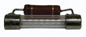
1R0 1W - wired across the metal bits of a dead fuse. The 1R0 resistor replaces the fuse element and allows you to check supply current by measuring the voltage drop across the resistor. The deal is 1V = 1A so you don't need to do any mental gymnastics while you are holding probes, and generally watching ten things at once.As far as 1R0 and 0R1 resistors for testing, what do I need to get?
Don't go any bigger than 1W. The reason is that if anything is faulty there is a delightful curl of acrid smoke from that resistor that ever so gently suggests you should turn it off, NOW!
Going to your other post, would it be worthwhile to ask Mike Elliot if he has a couple of Rev. B boards laying around, and cost?
Despite the scorn heaped on the APC in previous posts, the darn thing is not entirely useless in its advertised role as a protection circuit - just don't expect it to magically give you an indestructible amp. It reliably prevents failure from a speaker output short to ground (because it acts much faster than a speaker fuse could ever go open circuit) and it predictably defines the location of a number of critical parts. So it has its place.
But... you are still left with MOSFET outputs that are extremely difficult to replace if you ever need to. This is what Chris is focused on.
I just checked the rest of the MOSFETs and they appear the same. P channel measure ~2.85M leads reversed from N channel as expected, open the other way.
Alan:
I took a look at R1 on the bad board. It is mounted tombstone style. The upper portion of the lead had been burned away from the board, so it was open. On the good board, I ohmed that portion of the lead out and found it was directly connected to the S wire connection from the main board. So, I took a jumper lead and ran it from the open lead on the resistor to the S wire connection. Sources now measure 27K to GND instead of the previous 3.6M. I could solder a jumper wire in if you think it needs it.
Zeners replaced on the P channel now as well.
Getting the pinout for Q1 and will check it.
Last edited:
1R0 1W - wired across the metal bits of a dead fuse
Like this:
Attachments
Hi Fellas,
Sounds good so far.
Hi Alan,
Again, we work differently.
I use a variac and monitor what I'm concerned with. I use 2 W devices and higher sometimes so that I can run the amp as well without having to short across the resistor, or turn it off and replace the fuse. The 0.1 ohm value isn't difficult to figure out, and affects circuit operation less for higher current applications (class A stuff and tube amps).
You are right though. I figure get the amp part fixed or the computer matters not. The mosfets represent the highest potential effort and cost. The cost of the RMS converter IC makes it not worth repairing the analog computer in my view. Plus the added damage path in a more complicated circuit. Since these analog computers are all basically turned off in North America, they are useless and have been since the amp was new. However, it is nice to know they can be helpful at their most sensitive setting. Repairing the analog computer protection is worth consideration once that channel is working again.
-Chris
So, the Rev. B board was a result of a design flaw in the power supply portion for the APC on the Rev. A board? Sounds like a rather consistent theme here. And in a retail $4K amp, these Rev. A amps weren't recalled to be updated to Rev. B status? Further, is it your opinion(s) that the Rev. A flaw is a potential cause of the failure we are trying to fix here? I did mention that the inside of the amp was quite dusty. Could this have contributed as well?
At any rate, where to now? From what I recall, my brother said when the amp started crackling, popping and smoking, the left channel quit working. Not sure if it worked at all when his wife turned it on that day, and I think it started failing immediately. I had cautioned him about not leaving this on all the time, but he had been anyhow. On Thursday night, before the failure on Friday, he mentioned that the amp seemed to be running warmer than usual, so turned it off that night. His wife called him at work and asked if she could listen, so he told her to go ahead.
At any rate, would the L channel shutting down (when the APC started failing) be a result of the APC, or have we not found what caused this? I guess I'm asking, how to proceed now that the APC is disabled and I think the output devices may be alright? Do I wait until I can get a variac, and then proceed once I have gotten further guidance from you gentlemen as to how to go about starting it up/testing it and what to monitor?
Hi Chris,
The way I would proceed would be to disconnect that circuit for the time being. Then find a variac and slowly apply power while watching the current draw. With the relays pulled, the output stage will begin operating at a low voltage (you want this while troubleshooting). If your current draw is okay, try stopping at +/- 25 VDC to check some voltages. Then increase another +/- 10 VDC and measure again, and so on. Don't take the unit all the way up to normal operating voltage yet. That can wait until the relays are reinstalled. I'm talking about the main supply rails when I mention the +/- voltage readings. Just close to those numbers, not exact.
Once you have it all fixed, look for possible causes. Keep your mind focused on getting the amplifier repaired right now.
-Chris
Chris,
When you mention "disconnect that circuit", are you referring to the APC, or removing the bad channel board from the amp main board connections? Also, the relay is for the input signal from the main board tube section. There is one per channel. Is removing this necessary, or is shorting the input RCAs sufficient?
When you mention "disconnect that circuit", are you referring to the APC, or removing the bad channel board from the amp main board connections? Also, the relay is for the input signal from the main board tube section. There is one per channel. Is removing this necessary, or is shorting the input RCAs sufficient?
Hi Chris,
The way I would proceed would be to disconnect that circuit for the time being. Then find a variac and slowly apply power while watching the current draw. With the relays pulled, the output stage will begin operating at a low voltage (you want this while troubleshooting). If your current draw is okay, try stopping at +/- 25 VDC to check some voltages. Then increase another +/- 10 VDC and measure again, and so on. Don't take the unit all the way up to normal operating voltage yet. That can wait until the relays are reinstalled. I'm talking about the main supply rails when I mention the +/- voltage readings. Just close to those numbers, not exact.
Once you have it all fixed, look for possible causes. Keep your mind focused on getting the amplifier repaired right now.
-Chris
A few more important steps.
1. Remove the rectifier valve before doing anything - that way the valve stage is NOT powered and doesn't upset the bias of the output stage.
2. Discharge ALL the big supply caps using a 1k/10W resistor connected between rail and ground. You need to do this every time you power up and power down - get in the habit of doing this religiously. It will save you from a nasty (literal and figurative) shock.
3. Remove the rail fuses from the APC board on the good side - no point in risking that good channel while you are poking about. It is very easy to slip...
4. Reduce the quiescent current from its original setting before you apply any rail voltage. You do this by tweaking the bias pot VR101 which is found next to the relay that you removed from the main board. Two full turns CLOCKWISE will do fine - I usually wind it all the way back to zero but it will be easier for you if you just reduce the bias. This adjustment is pretty touchy, so the two turns is enough to significantly reduce the quiescent current. It is mush easier on the nerves to start with no current and work your way up.
With these points in hand, I would, as Chris suggests, monitor the supply current. I would also monitor the output dc offset.
With the relay out AND the valve rectifier removed, I would take the rails all the way to +/-70V. You have to do this at some point and this is a good time because...
The problem with having the relay in place is that it takes 90s for the mute circuit to open the relay from their 'failsafe' position and the relay timer and relay needs around 60% of rail (or more, component tolerance and all that) to operate. So you end up nervously increasing the rail voltage with your variac while waiting for the relay click and praying that that is all you hear or see. No flash from the sockets - no smoke from those 1R/1W resistors replacing the rail fuses. (A pox on your cursed 0R1 resistor Chris 😀)
Hi Alan,
God, you're funny! Thank you for that. 😀
Also, a great explanation as to the why of things. Totally agree.
Hi Chris,
I was speaking about the APC being electrically disconnected. Alan explained the answer to the relay question really well. I do this job as he suggested. It's difficult to post every step as it's all automatic for me. I do these things without really thinking about it.
Shorting the input jacks should be done whenever you are working with any amplifier (any device for that matter). The exception is a generator that is connected, but turned down.
From the sounds of things, Alan may power these circuits up a bit more quickly than I normally do. Another difference between two technicians. I would recommend you go more slowly only because he is more familiar with these amps than you would be. Extra caution. Me? I've had enough nasty surprises on the bench, and working with just about everything out there makes me a little more cautious. I've had a few capacitors go bang close to my head, a couple large can filters too. Maybe I'm a bit gun-shy?
-Chris
I think I will order this variac tomorrow or Friday. Can't find anything on craigslist, don't know where/when any hamfests, etc. are. Price seems reasonable even though it is probably china origin. They also have a 5A unit for $40 less.
Variable AC Output Transformer MAX.20A (Metered Variac) - eBay (item 120631655275 end time Nov-07-10 14:34:08 PST)
Variable AC Output Transformer MAX.20A (Metered Variac) - eBay (item 120631655275 end time Nov-07-10 14:34:08 PST)
I've been watching this thread with much interest as I have an SA-220 I picked up for a song a few years back that wasn't coming out of mute, but didn't seem to be damaged in any other way. I haven't taken the time to troubleshoot it and the info here will be very useful. Thank you to Chris and Alan for all your assistance to Pars... and to Pars for doing all the hard work.
After skimming all of this, I noticed noone had mentioned that Michael recently added a new alternative on the AltaVistaAudio site for replacement FETs for a SA-20/220:
A fifth option is to install Toshiba MOSFETs 2SK1530 (n-channel) and 2SJ201 (p-channel). These are 200V, 12A parts whose biasing requirements seem electrically compatible with the bias network in the amplifier. However, they are TO-3 plastic case, rather than TO-3 metal case parts like the originals, so a little extra work will need to be done to mount and wire them: their source and gate pins are in the right locations to pass through the holes already drilled in the heatsinks, but a bit of work will need to be done to get the drains wired up. I have no personal experience with these parts, but I've been told that some are using them successfully. However, it should be noted that like the original parts, these have a positive temperature coefficient and will most certainly need matching to assure equal current-sharing. The SA amplifiers are not wired up to allow easy monitoring of individual device drain currents, so the DIY installer should keep this in mind and consider wiring in source resistors to monitor currents to avoid current-hogging and possible thermal runaway.
If you find dead FETs, this might be a useful alternative to either old pulls or the Exicons. I also noticed that Musical Concepts, who had been touting the Exicons for Hafler rebuilds, no longer lists them and then I found this site that talked about issues using them in Hafler rebuilds:
Hafler (HITACHI) 2SJ49 and 2SK134 NOS Power MOSFET p (05/29/2009)...
So I maybe the Exicons are not a viable choice.
Also, when I've worked on amplifiers in the past, I've often used a series light-bulb in the AC line as a 'poor-mans variac'. While it only gives a good/bad indication, it has saved my butt in a few situations. Chris and Alan, what do you think of this for the casual repairer?
Then Chris, you mentioned a redesign of the SA100. Is this something you've published or are willing to share?
Finally, Pars, I noticed you mentioned an 'SA100 schematic that was floating around'. I had drawn one for the SA-12 back in the late 80's and had seen it 'floating around' (it was handdrawn on graph paper)... if this is an actual SA100 schematic, I'd love to see it as I have an SA-12 to get back in service someday. Pars, can you point me to it or send it?
Greg in Mississippi
P.S. I also have an NP220 rebuild from AltaVista. Even tube-rolling, it never grabbed me musically the way the SA-12 or the SA-20 (before I blew it and had it converted to the NP220!) did. I could be wrong, but it looked to have a pretty complex compound transistor driver stage... it seemed funny that it went from a 2-tube/channel setup with no driver stage to a 1-tube/channel with a lot of transistors in the driver stage.
- Home
- Amplifiers
- Solid State
- Counterpoint SA-220 problem...