Not yet. I don't get much time to play in the garage so I'm slow at this.Hi
Thanks for answering.
.
Did You measure Primary inductance of Output transformer maybe?
Thanks 🙂
Thanks for the kind words. I miss the kenpeter/Michael Koster discussions here. I learned so much from them.Just found this thread! Been wanting to try A2 for a while. Someday, I will! Followed a number of A2 threads here; pmillett and Michael Koster to name a few. Been collecting Eimac tubes for years for potential projects. Ran some 100TH & others in PP using Jack Iliano's driver transformer and an Edcor 100W 10K OPT (thanks Wavebourn!). Had to run the zirconium coated plates cherry red for a few hours to mop up gasses. Got to 100W but distortion products were a little high. Did not take notes back then, unfortunately.
Following and thanks for the great thread!
I'm sure you can clean up the distortion with the right feedback scheme on those 100TH. Beautiful tubes!
@trobbins,
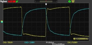
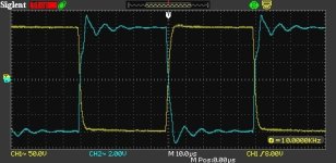
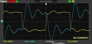
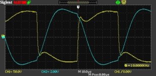
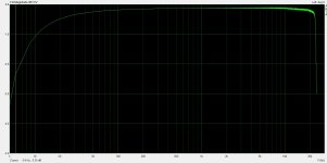
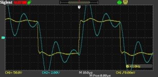
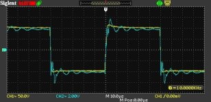
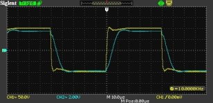
Ok, I think I have the compensation fairly optimized. I ended up with a 300pF cap and 34.2k resistor. Yellow trace is the plate of the output tube (where the feedback is sampled). Blue is the output transformer secondary. First picture is with 8 Ohms on the secondary. Second picture is with the secondary open. Stand by for tests with capacitors on the secondary...
Ok, I think I have the compensation fairly optimized. I ended up with a 300pF cap and 34.2k resistor. Yellow trace is the plate of the output tube (where the feedback is sampled). Blue is the output transformer secondary. First picture is with 8 Ohms on the secondary. Second picture is with the secondary open. Stand by for tests with capacitors on the secondary...
Attachments

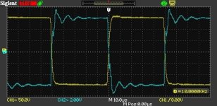
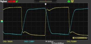
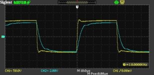
Next set of plots are with the secondary loaded with capacitors only. 1.5nF, 22nF, 100nF, and 330nF. 1.5nF looks pretty similar to an open secondary (slight change on the rising edge). As capacitance increases, you see increasing magnitude of ringing on the secondary with decreasing frequency. Makes sense. Since the transformer is outside the feedback loop, the feedback is only trying to control the yellow trace.
Attachments

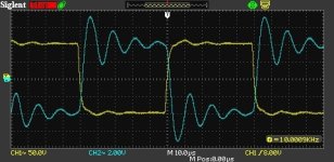
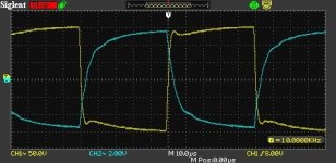
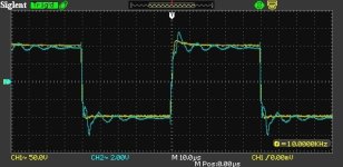
Next set of plots are with the secondary terminated with 8 Ohms and parallel capacitances. First is no cap, then 100nF, 470nF, and 2uF.
Things get pretty distorted, as expected, but no serious misbehaviors here.
Things get pretty distorted, as expected, but no serious misbehaviors here.
Attachments

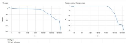
I figured out that my scope could measure phase between the two inputs, so I gave FR/Phase plots a shot. I just swept, recorded interesting points, and plotted from a spreadsheet. I probably need to buy a better signal generator that is flat to a higher frequency so that I can take these types of plots further up.
First plot is the amplifier input to output tube plate (everything in the feedback loop). Second plot is the output transformer primary to secondary.
I measured the output transformer primary inductance at 35.6H at 60Hz/1W.
Edit: I ordered a chassis from Landfall. Time to start working on getting this in a real box.
Attachments
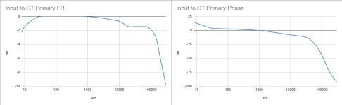
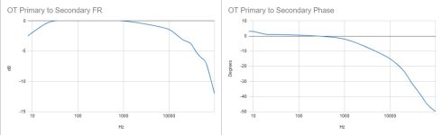
Well done for making a gain-phase plot - that's tough without automation. It was interesting to see the OT secondary plots, since they are decoupled from the feedback loop, so of no consequence for stability. What do you think is causing the -1.5dB droop and plateau? There must also be a main cause of roll off above 100kHz, apart from the 100kHz RC you recently introduced.
I think the -1.5dB droop and plateau is caused by the load that the OT presents, although the flat plateau area seems strange to me. The same feedback circuit with different compensation and the Electra-Print OTs had a much more ideal 10kHz square wave. All I changed was the OTs and I noticed the change in shape to the bump/dip/slow rise of the square wave above. After disconnecting the 8R load from this OT, I have a nearly ideal square wave on the output tube plate.
These are quite a bit bigger than the Electra-Print OTs. I also noted that the datasheet for the HQ-5090s shows all of the testing done on the 4 Ohm tap. I suspect that this OT is optimized for 5k:4 or 10k:8 operation, not the 5k:8 that I am testing. I noticed that my testing doesn't quite match the datasheet performance for FR/phase. Also the single small wire (compared to multiple wires for all the other taps) makes that tap look like an afterthought.
After I get this into a chassis, I will put together another amplifier with the Electra-Print OTs and the 826 output tubes I have. That should be fun.
Actually, the OT with the best HF performance that I played with was probably the Edcor, but it has been a while so I'm not totally sure.
I traded more than 6dB of feedback for more gain to get a bit lower input sensitivity and to make the biasing of the input tube easier, but the differential feedback on the op-amp that @zintolo mentioned might be a way to use the op-amp to get some more feedback in there, since I can't really increase the gain of the input stage any further. I'll have to think about it and see if it could work.
@SpreadSpectrum what I've learned on differential feedback is taken from a French DIY site: http://www.audiyofan.org/forum/viewtopic.php?f=60&t=9543
If you don't speak French, use this link: https://www-audiyofan-org.translate...r_sl=it&_x_tr_tl=en&_x_tr_hl=it&_x_tr_pto=wap
In Push-Pull amps it is really a nice feature, as you can adjust the DF with a pot (within a stability range) without affecting the sensitivity of the amp.
I'd like to try it in SE amps too, but by now the amp is on paper only due to some work trips and some other priorities at home.
As I suspected this is a very interesting amplifier design.
I really like how the P mosfet is used to apply feedback to the input pentode's cathode. This is a innovation for me.
Slick how it separates the feedback voltage from the pentodes AC current and the cathodes impedance to ground.
I was working on a phono input stage where low noise and gain was a key goal and struggled to find a way to add negative feedback to the input device without adding any impedance in the cathode as that degrades the noise figure and gain. The P mosfet may well be a useful answer.
Going to try it out.
I like the way you have paid attention to measured data to inform your design decisions.
I tire quickly of the "sounds great" but no measurement data designs.
Getting 19 watts of very clean power from your relatively low rail of 525 volts is impressive.
The DF with 0.7 ohms output impedance is a workable low for many speakers and this is without feedback around the transformer.
Is the grid of a 826 piticullary rugged that allows the positive drive (and so grid current) without failure?
Wondering about trying other tube types that could deliver high current with positve grid drive in triode mode.
Thanks for the excellent brain food.
The 826 is meant for grid drive. The datasheet gives various operating conditions, all of which feature considerable grid power dissipation.
There are probably better tubes to use, though. Lots of NOS 826 end up being gassy. One big name vender got kind of frustrated with me because I kept sending gassy tubes back. Not my fault, they kept sending gassy tubes (but they had no means to test them ahead of time). These weren't just a little gassy either, they were bottles of air and the filament went up in actual smoke when I applied power as it lit up.
Of all the tubes I tested, I think the new production 211 got lowest distortion and were super easy to acquire and reasonably priced. The various 100W tubes made the most power and looked the coolest, but I spent a lot of time acquiring, testing, and returning to build my stock.
Ok, I know I said I was done messing with this circuit but I went and messed with it again. I went back to a 510R lower feedback resistor. This adds 8dB of feedback back in. This also forces me to put a positive voltage on the 6BN11 grid since that raises the cathode up so much more. I decided to just use a 1.2V reference.
I've looked at some square waves and tweaked the compensation a bit and am going to try to redo all of the measurements I just did. I just bought a much better function generator to make that easier and to expand the upper limit of frequency I can reach. This should be fun.
I've measured Zout. It went from 0.63 Ohms to 0.53 Ohms, so damping factor went from 12.7 to 15.1. That's a worthwhile improvement.
I'm compiling the results from some soundcard testing. I'll post those soon.
Attachments

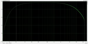
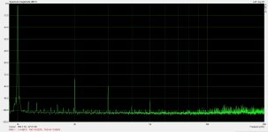
Ok, I did a series of distortion measurements at 1W across the audio band. Results are attached. Distortion falls above 10kHz but that's just because the distortion harmonics go above what the measurement setup can see.
I attached the distortion spectrum at 1kHz. The distortion harmonic character does not change as I sweep frequency so I didn't bother capturing pictures of all of the other frequencies.
I also attached a small signal frequency response measurement (and a measurement setup loopback test for reference). All of the distortion/FR measurements are measured across an 8-Ohm resistive load on the output transformer secondary.
I'll redo the gain/phase measurements/plots with my new signal generator next.
Attachments

"Someone on this forum once told me that once you start with transmitting triodes, you never go back, that is proving to be true for me..."
True, true. I made a pair of 811A SE monoblocks around twenty years ago and despite of several design flaws and a very limited budget, those big bulbs and their bright filaments made quite an impression on me. There was something about the sound too that has lived rent-free in my memory since then. Probably just a lucky mix of harmonics and an output impedance that suited the speakers I had well, but it it was closer to having dead rock and roll legends playing live in my room than anything I've experienced from more "civilized" amps later on.
Since a few weeks I'm pleased to welcome Elvis, Johnny, Lemmy, Jimi and all the others back into my listening room. I'ts probably just harmonics and damping factor again but I like to believe that the slightly radioactive filaments and the red hot plates in my new 808 SET are able to bring back the dead 😀

A much more primitive, old shool design than the Corona amp in this thread but it definitely does something right.
The power supply is still far from finished but I'm already collecting high mu TT triodes for my next project (Anyone who has Taylor T20 or TZ20 triodes for sale are most welcome to drop me a PM). My stash of new 300B tubes on the shelf behind me can wait, I expect them to sound rather dull compared to class A2 transmitter tube amps.
True, true. I made a pair of 811A SE monoblocks around twenty years ago and despite of several design flaws and a very limited budget, those big bulbs and their bright filaments made quite an impression on me. There was something about the sound too that has lived rent-free in my memory since then. Probably just a lucky mix of harmonics and an output impedance that suited the speakers I had well, but it it was closer to having dead rock and roll legends playing live in my room than anything I've experienced from more "civilized" amps later on.
Since a few weeks I'm pleased to welcome Elvis, Johnny, Lemmy, Jimi and all the others back into my listening room. I'ts probably just harmonics and damping factor again but I like to believe that the slightly radioactive filaments and the red hot plates in my new 808 SET are able to bring back the dead 😀
A much more primitive, old shool design than the Corona amp in this thread but it definitely does something right.
The power supply is still far from finished but I'm already collecting high mu TT triodes for my next project (Anyone who has Taylor T20 or TZ20 triodes for sale are most welcome to drop me a PM). My stash of new 300B tubes on the shelf behind me can wait, I expect them to sound rather dull compared to class A2 transmitter tube amps.
The 808 is a beautiful tube. I really wanted to use those instead when I was buying 826s but they are pretty expensive. Then I got the idea to use a 100W plate and fell in love with the 100T variants, many of which can be had cheaper than the 808.
I redid my gain/phase plots. This time I was much more careful to adjust out output variations in my signal generator (or my amplifier when I was testing the output transformer). I question whether my measurement setup is really able to measure these phase angles at really high frequencies. I have to go all the way up to 17MHz to get the amp to unity-gain and the phase goes every which way before it gets there. I just don't know whether to trust it, especially with different probes on the two channels.
I redid my gain/phase plots. This time I was much more careful to adjust out output variations in my signal generator (or my amplifier when I was testing the output transformer). I question whether my measurement setup is really able to measure these phase angles at really high frequencies. I have to go all the way up to 17MHz to get the amp to unity-gain and the phase goes every which way before it gets there. I just don't know whether to trust it, especially with different probes on the two channels.
Attachments

Yes, the 808 is a rather expensive tube and very rare in my part of the world, it took me almost 20 years to find three good pairs.
I regret to a degree that I lowered my ambitions over the years and ended up using them together with cheap guitar amp OPTs in a rather boring powder coated chassis but it was about time to finally got it done. At least it has a bit of that highly sought after "Late 40's Soviet telecom lab equipment" look... 😎
Next time I build something using tubes with TT filaments I'll probably lean more towards a more sophisticated style with shellaced teak frames and polished copper top plates.
I'm impressed by all the published measurements (and general level of knowledge) in this thread. I lack both the equipment and the knowledge to build amps with anywhere near these levels of negative feedback but fortunately both my main pairs of speakers sound better connected to amps with moderate damping factors.
Thanks! I've enjoyed learning to take measurements in this thread.
I have been testing my test setup and I hooked both inputs up to the same source and started seeing differences in phase on my scope at 1MHz. At 17MHz, there is like 25 degrees difference between the channels. I have to use a 100X HV probe for the output tube plate, so I'm not surprised that there are differences. It just casts doubt on everything in the above gain/phase charts above 1MHz. It was a fun exercise, though. Maybe I can work my test setup to improve that some day.
Attached are 10kHz square waves with various loads. Yellow trace is output transformer primary and blue is output transformer secondary.
To summarize, things look fairly similar to before adding more feedback, but primary waveforms look flatter on top. They have a little bit more overshoot peak, but the overshoot is still small.
Attachments


On the topic of "taming" hi Z transmitter triodes:
The Corona topoloy in this thread seems to be an excellent way to hold pretty much any output tube in an iron grip and squeeze some very impressive distortion and dampig factor numbers out of it, far into solid state territory except for a little bit of Zout left due to the DC resistance in the OPT secondary winding.
What if the ambition is allowed to be a bit lower, like applying local feedback around an 811A or similar to make it behave roughly similar to a 300B running open loop? I saw this schematic in a blog that I guess belongs to the thread starter and thought it should be possible to add a direct-coupled Nfet follower between the feedback resistors and the grid:

Ale Moglia did something similar here but with a coupling cap between the feedback network and the buffer, something I'd like to avoid if possible:
https://www.bartola.co.uk/valves/2022/03/14/811a-se-amplifier-with-a-twist/
The Corona topoloy in this thread seems to be an excellent way to hold pretty much any output tube in an iron grip and squeeze some very impressive distortion and dampig factor numbers out of it, far into solid state territory except for a little bit of Zout left due to the DC resistance in the OPT secondary winding.
What if the ambition is allowed to be a bit lower, like applying local feedback around an 811A or similar to make it behave roughly similar to a 300B running open loop? I saw this schematic in a blog that I guess belongs to the thread starter and thought it should be possible to add a direct-coupled Nfet follower between the feedback resistors and the grid:
Ale Moglia did something similar here but with a coupling cap between the feedback network and the buffer, something I'd like to avoid if possible:
https://www.bartola.co.uk/valves/2022/03/14/811a-se-amplifier-with-a-twist/
Yeah, that's my blog.
I would think your idea of putting a follower to drive the grid after the feedback divider would work well.
I made one KT88 amp based on the principle above and it worked quite well, but the bias applied to the mosfet gate had to be a pretty high negative voltage (as you can see in the figure). The fact that an 811A needs positive grid bias should make things work out better. P-channel mosfet bias will probably still work out to a negative voltage, but far less so.
One thing that I haven't written about much in this thread but should be mentioned is that there is one huge benefit to having the input stage of the amp included in the feedback loop and that is a very low noise floor. My single-stage feedback amps just have significantly more background hiss despite having similar sensitivity.
The black background on this amp is just really nice, and I think that is actually quite a bit more important than getting the distortion levels down this far.
Good to know, this is indeed what I experienced with the differential feedback. I’ve been told there’s a huge benefit on phase as well, but I can’t measure it.One thing that I haven't written about much in this thread but should be mentioned is that there is one huge benefit to having the input stage of the amp included in the feedback loop and that is a very low noise floor.
- Home
- Amplifiers
- Tubes / Valves
- Corona: An Ultra-Low Distortion A2 DHT SE Amp Prototype