H
HAYK

H
HAYK
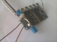
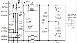
This is the TDA8932 in BTL. I took off the SMD capacitors after the coils and replaced them with 680nF63v EPCO ones with bias resistor 220ohm/2W.
NXP has adaptive dead time that they call it handshake, it keeps very low dead time. Other NXP ones pretend to be zero dead time, but STmicro fas a similar kind that applied in STA516 to announce 10ns minimum. Before modifying I was saying it is not bad at all, after modifying it sounds ultra clean sound with celestial choral voices that I say it is excellent amp. I had such result also with the Chinese TPA3110 2x 15W with 100 ohms/2W, but it has dry sound and not as spectacular as the this NXP.
NXP has adaptive dead time that they call it handshake, it keeps very low dead time. Other NXP ones pretend to be zero dead time, but STmicro fas a similar kind that applied in STA516 to announce 10ns minimum. Before modifying I was saying it is not bad at all, after modifying it sounds ultra clean sound with celestial choral voices that I say it is excellent amp. I had such result also with the Chinese TPA3110 2x 15W with 100 ohms/2W, but it has dry sound and not as spectacular as the this NXP.
Attachments
AD seem to have some "crossover" distorsion that ADB don't have. But it seems that ABD has more noise!? How do one mitigate that?
//
//
H
HAYK
It is not noise, The capacitors on the simulator were too low to clear the 2x carrier frequency. If you keep the same LC values of AD mod than the 2x carrier will be much less in ABD mod.
I would like to know the details how you created the plots in your opening posting. I agree that deadtime is a source of distortion but I am in doubt whether all your conclusions are correct. Btw actual THD measurements of standard TPA325x-amps are below 0,01%. Can you show a THD-measurement with and without your modification?
H
HAYK
This idea I developed on a fertile website you can follow it step by step.
https://www.eevblog.com/forum/projects/minimizing-the-class-d-distortion/
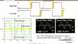
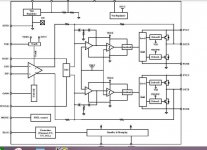
What concerns the class AD and AB mod you can find in various documents as the picture bellow from infineon class D document.
The AD and BD graphs are not correct as I lowered the output filter frequency to clean the carrier and see better the anomaly, which is worst in reality. What concerns the ABD mod I over increased the filter frequency to see exactly the linearity, this why you see the 2x carrier as noise.
The distortion on AD mod is only 2.2% in open loop, if as Purifi you apply 90db NFB, you get very low number but the class D signature remains.
In TPA325X series TI has a patent probably applied which detects when, the inductive current goes short and applies a dc offset to input signal whose value is determined by a charging capacitor that I ignore by which interval, by this only one clock cycle the output goes flat to recover on next cycles. I ordered a board of it, I will see how does the error corrector will react in ABD mod.
https://www.eevblog.com/forum/projects/minimizing-the-class-d-distortion/
What concerns the class AD and AB mod you can find in various documents as the picture bellow from infineon class D document.
The AD and BD graphs are not correct as I lowered the output filter frequency to clean the carrier and see better the anomaly, which is worst in reality. What concerns the ABD mod I over increased the filter frequency to see exactly the linearity, this why you see the 2x carrier as noise.
The distortion on AD mod is only 2.2% in open loop, if as Purifi you apply 90db NFB, you get very low number but the class D signature remains.
In TPA325X series TI has a patent probably applied which detects when, the inductive current goes short and applies a dc offset to input signal whose value is determined by a charging capacitor that I ignore by which interval, by this only one clock cycle the output goes flat to recover on next cycles. I ordered a board of it, I will see how does the error corrector will react in ABD mod.
Attachments


Referring to your link: So the idea is to avoid the discontinuity by nullifing inductive output current. This scheme comes with some drawbacks I personnally do not like:
-a power dissipating damping resistor
-designed and tuned for resistive load - there is no speaker with resistive impedance at 500kHz
-higher clock harmonics are not suppressed at all.
-R, C & L with all their tolerances must match pwm-clock frequency
-a power dissipating damping resistor
-designed and tuned for resistive load - there is no speaker with resistive impedance at 500kHz
-higher clock harmonics are not suppressed at all.
-R, C & L with all their tolerances must match pwm-clock frequency
Last edited:
Your proposal with a common damping resistor in the caps return path may be the better approach, shorting at least differential mode noise. As far as I do remember I tested my TI-class-d-amps with output filter caps floating but found stability issues in that case. May give this another try...
H
HAYK
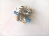
I converted the Chinese TPA3110D2 PBTL 30w with great success. It required 130 ohm 3w. The sound is finest of all, I never heard the requiem of Mozart in mp3 with such resolution. The NXP TDA8932 board doesn't reproduce deep bass sounds although many praise for it. I paralleled the output SMD capacitors taken off with the input ones, added 4700uF low ESR on the supply, just a little better punch but no 40hz that fills normally my speakers the living room.
Unlike the 2x15w TPA3110 which has strange logo, this has TI logo but wrong placed. for a $1.5 a board luckily not to expect original TI. I say luckily because with original TPA3116D2 in PBTL, I couldn't get it sounding such refined sound. The Chinese has found a better transfer function than the original, this what I think the reason is.
Unlike the 2x15w TPA3110 which has strange logo, this has TI logo but wrong placed. for a $1.5 a board luckily not to expect original TI. I say luckily because with original TPA3116D2 in PBTL, I couldn't get it sounding such refined sound. The Chinese has found a better transfer function than the original, this what I think the reason is.
Attachments
H
HAYK
While I am discovering new sounds from TPA3110 PBTL, I start converting the TDA7498e board, 12$.
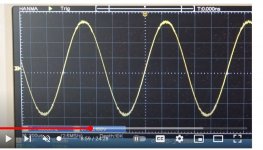
At first glance on the guts, it shows two separate outputs from oscillator feeding each branch, so probable the carriers are of opposite phase. Looking the output filter with a common 1uF and individual 220nF along with snubbers, it is surely an opposite phase AD mod. Searching on Youtube, I saw the wave bellow, the carrier residual becomes visible only at high levels, this is the signature of BD mod. This why I bought it. If I analyze the output filter, the 1uF and the coils form the BD mod, but the designer with 220nF capacitors on each branch instead of a resistor as I do. The inductance and low capacitance form low impedance resonance near carrier frequency. I tried this way of biasing, although The switches can toggle at zero current, the chip TPA3116 was running very hot. On eevblog website no one could give any explanation. Instead of heating the chip, I opted for a heating resistor that can bias without resonance.
I will take off the three yellow capacitors and replace them with a pair of 680nF and a resistor, not so difficult.
Attachments
H
HAYK
I listened this amp about half hour non modified with great disappointment. Passing from the precedent spectacular amp to this as if I switched on a radio. But the purpose is to make it better not the best. What can get better by converting into ABD mod by resistor instead of capacitors is the high frequency grain. If I stopped listening after half hour because my ears got whistling. It has a high frequency grain that sounds rather agreable at long it makes the sound bright. By converting, it lost the grain and became more comfortable, this is the only enhancement I got.
I don't advise you buy this amp if power is not important, because its transfer function two poles with single op amp is good for motor controllers but it is far less performant than double op amp used in TPA's.
To convert, I took off the three yellow capacitors and cut the tracks linking the R to C of the SMD snubbers. Added a pair of 680nF/63v. A single 3W 220 ohm is sufficient to bias, I add in // another 220 ohm with no any effect.
To note that I am using with 30v supply.
Attachments
Very interesting HAYK.
So you did not post a 100% clear schematic of this technique, but what I can read is:
1) split the parallel capacitor in two (each of 2x original value to maintain the original filter response)
2) load/tie the split via a resistor to ...ground/0V? (please confirm)
3) resistor value is between 100 Ohms and 130 Ohms... How is this determined? By calculations or by experimentation?
Thank you in advance
H
HAYK
Thank you for your interest in this subject.
When it runs in ABD mod, as BD mod the carrier frequency doubles, for this the value of the capacitors can be lower than the original. I am using for now 2*680nF used habitually with 10uH 4 ohm and 20uH 8 ohm as the frequencies are 300khz. For high power amps may be a Zobel be needed.
What concerns the biasing resistor, it depends on the dead time (unknown), the supply voltage, the frequency, in short, incalculable only by measurement of the distortion at low power or simply by lowering the value gradually until no significant improvement is achieved. The TDA8932 which has very low DT, with 22v supply only 220 ohm was sufficient whereas the TPA3110 with 26v it needed 130 ohm. The TDA3116 needed 100 ohms. You can go lower if you want but heat uselessly.
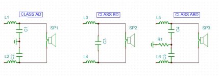
The circuit of ABD mod is on the first post along the other two mods.
When it runs in ABD mod, as BD mod the carrier frequency doubles, for this the value of the capacitors can be lower than the original. I am using for now 2*680nF used habitually with 10uH 4 ohm and 20uH 8 ohm as the frequencies are 300khz. For high power amps may be a Zobel be needed.
What concerns the biasing resistor, it depends on the dead time (unknown), the supply voltage, the frequency, in short, incalculable only by measurement of the distortion at low power or simply by lowering the value gradually until no significant improvement is achieved. The TDA8932 which has very low DT, with 22v supply only 220 ohm was sufficient whereas the TPA3110 with 26v it needed 130 ohm. The TDA3116 needed 100 ohms. You can go lower if you want but heat uselessly.
The circuit of ABD mod is on the first post along the other two mods.
Attachments
Thank you for the explanation.
(Sorry I missed the schematic in the first post.)
This is definitely something to try out.
(Sorry I missed the schematic in the first post.)
This is definitely something to try out.
A question about the power rating requirement of the resistor. It would seem the AC signal amplitude that develops across the resistor would come from the voltage appearing at it’s junction with the two filter capacitors, which itself would be due to the residual common-mode error as a function of the output filter component value mismatches? If true, wouldn’t that amplitude be relatively low, so the power dissipated power also relatively low? Requiring a relatively low power rating for the resistor?
H
HAYK
This conversion is only applicable upon BTL and in phase carriers of same clock, Those with inverse carriers or bridged auto oscillators can not be applied. As the two branches are in phase, the output doesn't see the carrier but the grounding resistor sees the carrier from both branches. The signal on the resistor is nearly the square wave with +/-Vcc/2 amplitude slightly filtered by the coils. The function of the resistor is to add some ac bias current to the coils and the peak current is Vcc/2R hence it dissipates V²/4R. Taking a margin of 50% the minimum power of the resistor becomes 1.5*V²/4R.
H
HAYK
The TDA7489e board had a bottleneck that was suffocating the sound, the volume pot. This is differential input, if one is grounded, the other must be driven by a low impedance source. The designer to put quality logarithmic pot. he(she) chose 50k B. I installed an external 3k B, the sound got revived, with first notes gave the sensation of ultra cleanness as the others did. To know that this amp 2*65W/8ohms, costs 12$ with ship. the pre COVID price of a pair of LM3886 with by far, faaar superior quality. Add to it 8.5$ 36v/7A.
https://www.aliexpress.com/item/100....order_list.order_list_main.10.21ef1802fGr6t7
https://www.aliexpress.com/item/100....order_list.order_list_main.10.21ef1802fGr6t7
H
HAYK
Maybe, If the outputs are in Phase. If you don't have a 2 channel scope, apply a resistor of 560 ohms 1/4W between the coils, Chip side and see if it remain cold. If hot, it cannot.
H
HAYK
I powered the TDA7498e with the $8.5 36v7A power supply with the earth* linked to ground. The 220 ohms now is biasing to perfection. The open loop gain of class D amps is in direct proportion with the supply voltage, this why it is important to apply the advised operating voltage.
I will receive in few the TPA3255. The DS shows in a table the phases of the outputs corresponding to four modes. I must switch to 4* SE mode, by ungrounding the 2 mode pins, to have the channel A and C in phase also B and D paired. This will require to swap the inputs and the outputs of B and C by cutting tracks and cross linking, not difficult.
*( It doesn't treat the earth for common mode filtering, better to add an external $1.5 EMI suppressor.)
- Home
- Amplifiers
- Class D
- Convert your class D into ABD modulation