Eual loudness graph for different low frequencies
Hi there E: Recommend reading Linkwitz's Thor sub project (Google it). Good reading for general information on sub's. The final graph for equal perceived loudness, in Phons, is directly applicable to any sub woofer project. Using this graph, my lowly project would need 100db to attain 90 db to equal loud listening level at home. Since the graph only goes to 20hz you will have to extend the graphics to obtain (or estimate) for 15hz. Hope your project is on track and look forward to your posts, keep cool with all the fire power directed your way. ...regards, Michael
...I have Windows 10, and 2010 Excel. ...
Hi there E: Recommend reading Linkwitz's Thor sub project (Google it). Good reading for general information on sub's. The final graph for equal perceived loudness, in Phons, is directly applicable to any sub woofer project. Using this graph, my lowly project would need 100db to attain 90 db to equal loud listening level at home. Since the graph only goes to 20hz you will have to extend the graphics to obtain (or estimate) for 15hz. Hope your project is on track and look forward to your posts, keep cool with all the fire power directed your way. ...regards, Michael
M-Force
As this is an outdoor application, there is no room gain to help out; but of course there are no room modes to deal with either. As the driver displacement required to deliver a constant output increases inversely with the square of frequency, going lower into a declining horn load, quickly becomes a 'rope push uphill'. To address this issue, Powersoft's M-Force 01 driver [1, 2 & 3] represents a very good candidate. I will have more information on this unit and its companion electronics later this week. WHG
[1] M-Force - Powersoft Audio
[2] http://www.diyaudio.com/forums/subwoofers/268269-powersoft-m-force-specs-now-available-2.html
[3] Powersoft M-Force - More details - Speakerplans.com Forums - Page 1
Hi j.michael droke,
Post #1122: "... Linkwitz's Thor sub project...final graph for equal perceived loudness, in Phons, is directly applicable to any sub woofer project...."
During the recording process the frequency response is already equalized for "loudness", if you play back the music at a similar level to that which the recording engineer listened to, you "only" need a flat frequency response; if you listen at considerably louder levels you might have to turn the bass down...")
Regards,
Post #1122: "... Linkwitz's Thor sub project...final graph for equal perceived loudness, in Phons, is directly applicable to any sub woofer project...."
During the recording process the frequency response is already equalized for "loudness", if you play back the music at a similar level to that which the recording engineer listened to, you "only" need a flat frequency response; if you listen at considerably louder levels you might have to turn the bass down...
Regards,
Hi j.michael droke,
Post #1122: "... Linkwitz's Thor sub project...final graph for equal perceived loudness, in Phons, is directly applicable to any sub woofer project...."
During the recording process the frequency response is already equalized for "loudness", if you play back the music at a similar level to that which the recording engineer listened to, you "only" need a flat frequency response; if you listen at considerably louder levels you might have to turn the bass down...
Hi there Oliver: Thanks for the response and good news. Sorry about the late reply, we just returned from the beach, where I do not have internet access. Verizon to the rescue with Fios optical line next year. Thanks again...Michael... PS too bad we are not hering from the OP, really interesting thread and postings. JMD
Last edited:
I was giving the thread some cool down time, as the moderators were becoming irritated. . . .too bad we are not hering from the OP, really interesting thread and postings. JMD
I need some help narrowing down my final design.
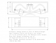
Option 1 below are side-by-side stereo 15 Hz exponential bass horns. I’ve chosen a 3:2 aspect ratio for the horn mouth. The points of interest in this design, are a flat slab construction of the horn’s bottom & top (approximately a 20 degree taper/conical expansion). The vertical side-walls are curved, providing the proper exponential area-expansion. Note: sketch is not to scale, and horn dimensions are not finalized - this is just an example for construction layout method.

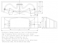
Option 2 below is also side-by-side stereo 15 Hz exponential bass horns, with the same 3:2 aspect ratio for the horn mouth, the same 20 degree flat bottom and top walls. The points of interest in this design however, are that the horns share a common center wall. Note that the center-axis of each horn (shown) follows an exponential curve, which is roughly half the rate-of-curvature of the outer walls.

Discussion: I suspect option 2 would have less lobing issues than option 1. However higher frequencies would tend to beam to the right & left (i.e. outside) of my listening area with option 2. I suspect if I kept my crossover frequency low enough, this wouldn’t be an issue. Either option is doable. However option 2 would likely be the easiest to construct (by having to cast only two exponentially curved walls, in lieu of 4). Opinions?

The horns will make a 10 degree angle of inclination with the ground plane (assuming I do not tilt them back to minimize, or even zero this angle). Assuming I keep the 10 degree angle of inclination, which of the above sub-options is best for loading the half-space plane? Or does it matter with giant bass horns?
Option 1a is with the horn mouth tangent with the earth.
Option 1b is with the horn elevated, with some vertical wall between the earth.
Option 1c is self explanatory.
Option 1d ???
Last edited:
I’ve chosen a 3:2 aspect ratio for the horn mouth.
Nice - better than tall-and-skinny. You want good contact with the ground plane to get the half-space thing happening.
The horns will make a 10 degree angle of inclination with the ground plane (assuming I do not tilt them back to minimize, or even zero this angle).
What do you think you'd gain with the 10 degree angle?
You can't build a heavy structure on freshly moved earth, therefore building any of your pictured 10 degree options would require filling in the gap between the horn and the ground with literally tons of concrete. This would be a fair bit of work and expense, and I don't see that it would gain you anything.
1a is the best of what you have pictured. The other two would introduce what, in an indoor system, would be called floor bounce.
...but I'd modify 1a by reducing the tilt to 1 degree - just enough for drainage.
You can't build a heavy structure on freshly moved earth, therefore building any of your pictured 10 degree options would require filling in the gap between the horn and the ground with literally tons of concrete.
The horns are going to have foundation abutments (reinforced footers) which are not shown in the sketch. The vertical walls will tie into the footers, which will directly support the vertical walls and overhead slab. If I cast the horn bottom in a similar fashion to the top, it would technically not require backfilling. I'm not saying I won't be backfilling, but rather that the high load-bearing portions of the horn will be resting on undisturbed soil. Tomorrow evening I'll post a more detailed sketch, showing the actual thickness of the horn castings, and how they'll tie into the foundation abutments. The bulk of the horn's mass is contained within the last 1/4 of the horn (aka the mouth region). The exponential expansion causes an exponential increase in weight per linear foot down the axis of the horn.
We had a potluck today at work, and I was discussing my horns with a civil engineer (her senior design project was to design a bridge, completely out of reinforced concrete - pretty cool. . .) The topic of discussion was whether or not I'd need to pre-stress the rebar in the top slab of my horns. The short answer is no. With adequate wall thickness (likely in the 10" thick range), and sufficient amounts of steel reinforcement, I will be able to safely park a 1-ton 4x4 truck on top of my horns, without pre-stressing the rebar. . .
The 10 degree angle of inclination is the result of keeping the horns center-axis parallel with the ground plane. If I join the bottom of my horns with the ground plane, then my horn's center axis is shooting into the air at 10 degrees (or 9 degrees, if I keep a 1 degree angle of inclination for drainage). A rise of 10 degrees is quite a bit over distance. I don't want the sound to overshoot. Granted - we're talking about giant bass waves, and it's probably not that big of deal down low (90 Hz crossover) - but if I crossover at 150 Hz, 10 degrees might be a problem. . . . The horn will have some degree of directivity at 150 Hz. The directivity problem is a valid concern between choosing Option A and Option B - independent of the 10 degree angle of inclination - as it relates to lobing, and upper usable crossover frequency. I'm stuck between choosing Option A, or Option B, and I'm open to a potential Option C also . .. ???
Last edited:
If I join the bottom of my horns with the ground plane, then my horn's center axis is shooting into the air at 10 degrees (or 9 degrees, if I keep a 1 degree angle of inclination for drainage). A rise of 10 degrees is quite a bit over distance. I don't want the sound to overshoot. Granted - we're talking about giant bass waves, and it's probably not that big of deal down low (90 Hz crossover) - but if I crossover at 150 Hz, 10 degrees might be a problem. . . . The horn will have some degree of directivity at 150 Hz.
Based on smaller horns, I think a flat base should be fine; at 10x the cutoff frequency of the horn, the sound 'beam' will still be at least as wide as the angle of the horn walls.
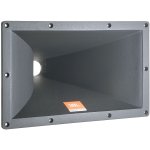
e.g. this JBL unit is a midrange horn with approximately the shape you are proposing - almost all the curve is in the side walls, the top and bottom are very close to being flat & 20 degrees is the nominal vertical angle.
https://www.jblpro.com/pages/pub/components/2386.pdf
At 4kHz - 10x the horn's cutoff frequency - the vertical beamwidth is still 25 degrees.
Why not make a rough pair of 1/10 scale 150Hz horns from scrap ply (or even a few layers of cardboard) to test this for yourself?
A mic at 5m should give you far field info for your full-scale build.
Attachments
I got curious, and made a mock-up myself, using scrap ply to build up the 'floor plane' and a horn like the 2386, at different angles to that floor plane; basically a 1/30th scale model of what you're proposing
This trial indicates my earlier surmise was wrong. The bottom 2 octaves were the same, but your 1a proposal was clearly the best above that (I tried 1a, 1c and my idea).
Of course if you built a decent midbass horn to try this stuff out for yourself, your testing will be more to scale, and truckloads more valid than mine.
Also, since you have to build big midbass units at some point, why not do it first? The lessons you learn could save you a lot when it comes to the big ones.
If the two bass horns are close together relative to the wavelegth they are reproducing, then the two horns reinforce each other.
If the bass horns were fed with a signal that had a phase difference, then there would be destructive interference and you would lose some or all of the "reinforcement effect".
If the bass horns were fed with a signal that had a phase difference, then there would be destructive interference and you would lose some or all of the "reinforcement effect".
A model like that was produced by JBL and it was not very good afaik.
The Paragon, as its name suggests, was the flagship model of the JBL product line for several decades. The ones that I auditioned, both JBL & DIY built, sounded a lot better than your "afaik" characterization would suggest.
WHG
Last edited:
Wise?
For Project Extraordinaire, wise is not an applicable notion.
This is Disneyland stuff without the commercial incentives built-in.
Note that structures this size come with acoustics of their own that cannot be fully appreciated or evaluated outside the realm of the designer's imagination, until built.
When built, no matter what design specifics are chosen for the bass horn(s), the acoustic and visual impact will remain primarily the result of scale only.
Integration with the rest in a manner necessary to present a coherent acoustic image is where the action is.
RR's design will do this in a way unavailable to other system configurations, while also delivering a structure with an aesthetic visual appeal and extreme seismic resistance.
That is why it is being presented here as a option worthy of consideration.
WHG
Wise to anticipate the post-operational testing strategy and to try to reduce impediments to meaningful testing and interpretation.
For example, if there are two horns to be compared singly and together (for example, to find the reputed interference spots).
B.
For Project Extraordinaire, wise is not an applicable notion.
This is Disneyland stuff without the commercial incentives built-in.
Note that structures this size come with acoustics of their own that cannot be fully appreciated or evaluated outside the realm of the designer's imagination, until built.
When built, no matter what design specifics are chosen for the bass horn(s), the acoustic and visual impact will remain primarily the result of scale only.
Integration with the rest in a manner necessary to present a coherent acoustic image is where the action is.
RR's design will do this in a way unavailable to other system configurations, while also delivering a structure with an aesthetic visual appeal and extreme seismic resistance.
That is why it is being presented here as a option worthy of consideration.
WHG
Last edited:
The "new" LAB 12 was designed around the turn of the century, I was late to the party and got my first units July of 2003, my first purchase of a horn driver with such a low FS and super stiff, heavy cone.
Prior to that, Tom Danley's servo-motor belt drive units had far more displacement potential than professional drivers, though by the mid 1990s they had been rendered obsolete by drivers such as AuraSound's 1808, the 1997 spec sheet copy below. Funny, (in retrospect) I was so caught up in driver "sensitivity" specifications back then that I paid little attention to their displacement- the AuraSound 1808 had considerably more than a pair of LAB 12", though the LAB 12 had more displacement per dollar.
I had mostly forgot about how advanced the 1808 was until 2015 when I started scanning old documents to eliminate hundreds of pounds of paper before moving cross country. Although the 1808 has great displacement capability, the mms is/was too low for low distortion in high compression ratio applications, something that does not show up in simulations, but can also result in ripped or kinked cones when pushed to Xmax.
Eminence has not made much advancement in LF horn drivers since the introduction of the LAB 12, but B&C and many smaller companies have, sold off my last (spare) LAB 12 last year.
I was contacted by PM several years ago on this forum by a man who wrote he had purchased the old Aura neo magnet structures, and was planning to re-issue drivers. I was unable to get a response back, and could find no web presence of his enterprise, a shame, as the 1808 magnet structure is still one of the best designs.
Art
You might be thinking of Seismic Systems in Redondo Beach CA, run by a guy called Barry Bozeman -- I got an 8196E (their updated to 1100W version of the Aura 1808) in 2002 and it's still going strong, he also had a version with a honeycomb kevlar cone.
Megagon Rev.01
Still working on it when spare time permits. WHG
See attach drawing and related patent for details.
WHG
Still working on it when spare time permits. WHG
Attachments
The Paragon, as its name suggests, was the flagship model of the JBL product line for several decades. The ones that I auditioned, both JBL & DIY built, sounded a lot better than your "afaik" characterization would suggest.
WHG
I don't know what you find to sound good, each to his own. I just know Harman hired Floyd Toole because of products like this.
- Status
- This old topic is closed. If you want to reopen this topic, contact a moderator using the "Report Post" button.
- Home
- Loudspeakers
- Subwoofers
- Concrete Bass Horn Design Question