Russ White said:[..]
And use the image from post #3 to guide you. 😀
R3 and R4 are correct on the board(and on the image I refer to) they were just not correct in my initial old BOM.
The BOM on post #101 is correct if you need the cap values.
Cheers! [/B]
Got it! Thanks 🙂 I'm now unconfused

Michael
Hi Russ
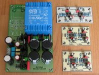
All the boards are finished!🙂
Next step is to give them a decent home. Didn't found anything useful up to now. Is it a wise idea to put some cap's on the outputs to block out any DC? To attenuate the volume I only have a blue 100K Alps stereo pot and two mono cermet 50K Bourns potmeters at hand. I guess the 50K's are preferred here or should I go even to a lower value?
Regards
Attachments
GeWa said:Hi Russ
All the boards are finished!🙂
Next step is to give them a decent home. Didn't found anything useful up to now. Is it a wise idea to put some cap's on the outputs to block out any DC? To attenuate the volume I only have a blue 100K Alps stereo pot and two mono cermet 50K Bourns potmeters at hand. I guess the 50K's are preferred here or should I go even to a lower value?
Regards
As long as there is no DC on the input there will be none(or next to none) on output. If you think you might have a source with DC, I would put a ~2.2uf cap directly after your 100K alps pot. I have had better success with 10K stero pots, but the 100K should work fine. I really like the little 9mm 10K stereo pots Jaycar sells.
You could put a cap on output if you like, but you should not need to. I would just check for DC on the output when you power it up connected to your source, but not your power amp.
Cheers!
Russ
PS, I hope you get a chance to hear it soon!!! 🙂
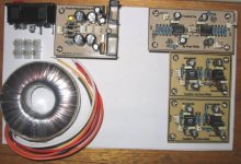
maf_au said:Mine are finished apart from a couple of 10pf ceramics and a couple of 2pin headers.
Here they are overlaid on a piece of paper the size of the box I have selected.
With a bit of wiring and mucking around, should be going in a day or so...
You can safely omit all of the ceramics on the freebird, and the RF filter 10pf on the yardbird if you are itching to test it. 🙂
Looking good man! 😀
Cheers!
Russ
Yardbirds are full house, I thought the 10pf on the freebird sounded like a good idea, already decided to omit the 20pf C5/C11.
With my tranny, I have dual secondaries. How should I connect that to the 3 input pins on the PS? It's a Jaycar MT2086 15-0 0-15v
Regards,
With my tranny, I have dual secondaries. How should I connect that to the 3 input pins on the PS? It's a Jaycar MT2086 15-0 0-15v
Regards,
According to the scpec sheet on Jaycar's site for that trafo, you would join the red and white leads (4 and 5) so that the two secondaries are in series, you then would run a tap wire where you joined those two wires, that is your center tap now, and will be your GND. The two remaining secondary leads (3 and 6, yellow, and purple) are your AC1 and AC2.
That trafo should work out very well.
Cheers!
Russ
That trafo should work out very well.
Cheers!
Russ
😱 Free- and Yardbirds popping up all over the place now!😀
Gonna see if I can lay my hands on a 50 or 10K stereo pot first before I continue. Maybe another dumb question but which type of potmeter is best as a volume attenuator, linear or logarithmic?
Cheers
Gonna see if I can lay my hands on a 50 or 10K stereo pot first before I continue. Maybe another dumb question but which type of potmeter is best as a volume attenuator, linear or logarithmic?
Cheers
GeWa said:😱 Free- and Yardbirds popping up all over the place now!😀
Gonna see if I can lay my hands on a 50 or 10K stereo pot first before I continue. Maybe another dumb question but which type of potmeter is best as a volume attenuator, linear or logarithmic?
Cheers
Hmmm which is better is a difficult question... 😀
But I prefer to use a good log pot. I like the 10K alpha stereo log pots from Jaycar a lot, they have a great taper, and sound to me better than the alps. And they are about $5.00US apiece.
Cheers!
Russ
Thanks Russ,
And while I'm getting my newbie training, 🙂
What's the best way of crimping these mini crimp pin connectors? (my pliers are too big) Fine needle-nose, or is there a special tool?
Do you solder them as well?
And while I'm getting my newbie training, 🙂
What's the best way of crimping these mini crimp pin connectors? (my pliers are too big) Fine needle-nose, or is there a special tool?
Do you solder them as well?
maf_au said:Thanks Russ,
And while I'm getting my newbie training, 🙂
What's the best way of crimping these mini crimp pin connectors? (my pliers are too big) Fine needle-nose, or is there a special tool?
Do you solder them as well?
I just use a needle nose to get them to stay, then solder. 🙂 Takes a little practice, and just a tiny amount of solder, use the fine stuff. Just try to keep them pretty straight.
Cheers!
Russ
GeWa said:😱 Free- and Yardbirds popping up all over the place now!😀
Cheers
Yea. The guys down at the electronics shop rub their hands when they see me coming in 🙂
I'm loading it all into one box, with the yardbirds output doubled to a headphone jack on the back. I'm interested to hear the difference between the two designs on my existing amp and the Mauro, which should be going later this week, all being well.
Ultimately, the yardbirds will probably grow their own case and become a headphone amp for my teenager who spends his life with them on. Well, assuming he hears a difference - he's currently listening to the onboard sound on an athlon motherboard via some good Sennheiser headphones he suckered me into. Might have to check out a decent soundcard as well...
Got one of those Jaycar 10k mini log pots. Is it worth the bother to mount it on an extension to minimise the length of the signal wires?
Michael
maf_au said:
Got one of those Jaycar 10k mini log pots. Is it worth the bother to mount it on an extension to minimise the length of the signal wires?
Michael
Well... it could'nt hurt, but I don't think I would bother.
Russ White said:I just use a needle nose to get them to stay, then solder. 🙂 Takes a little practice, and just a tiny amount of solder, use the fine stuff. Just try to keep them pretty straight.
Cheers!
Russ
Ok, that's working. Careful use of the sidecutters does the job... 😀
The two remaining secondary leads (3 and 6, yellow, and purple) are your AC1 and AC2
Is order important with those two? (the yellow and the purple) Will it catch fire if I have them the wrong way around? the connector doesn't seem to have a polarity apart from 0V in the centre - my guess is that the diodes sort the AC, so it shouldn't matter, but I'm working from minimal PS knowledge here...
maf_au said:
Is order important with those two? (the yellow and the purple) Will it catch fire if I have them the wrong way around? the connector doesn't seem to have a polarity apart from 0V in the centre - my guess is that the diodes sort the AC, so it shouldn't matter, but I'm working from minimal PS knowledge here...
Nope, you can put the two on either end without out worry. The only one to take care of the is 0V(center tap) in the center. You had it right. 😀
Cheers!
Russ
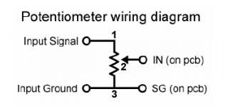
Potentiometer wiring.
My pot is the jaycar 9mm mini device 10k log.
Dealing with these tiny pins... I have some veroboard to make it a bit easier.
According to the BrianGT nigc users guide:
My pot is the jaycar 9mm mini device 10k log.
Dealing with these tiny pins... I have some veroboard to make it a bit easier.
According to the BrianGT nigc users guide:
- Incoming Signal (centre pin of RCA) goes to pin 1 on the pot
- Pin 2 on the pot goes to signal in on the PCB.
- Signal in ground goes to pin 3 on the pot and from there to Sig Ground on the PCB.[/list=1]
Assuming pins are numbered left to right when viewing the pot from the knob end with the pins pointing upward...
Diagram from the nigc users guide attached.
Attachments
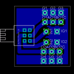
maf_au said:Never mind, I just found Russ's PCB for that pot, which explains everything - I had it backwards...
Jaycar should sell those boards as an accessory...
The illuminating circuit board reveals all:
Hi Michael,
Just remember that the picture you see there is from the top, so the pins are pointed down. 🙂

Cheers!
Russ
Russ White said:
Hi Michael,
Just remember that the picture you see there is from the top, so the pins are pointed down. 🙂
Cheers!
Russ
Oh...
So I was right the first time? Bugger!
I think I better buy some of those boards off you next time we do business.. 🙂
Michael
Yep viewing the pot with the pins up and the knob end toward you starting from left to right
pin 1 Signal
pin 2 OUT
pin 3 Signal Ground
Sorry if I answered you too late. Just ate my breakfast a little while ago. 😀
Cheers!
Russ
pin 1 Signal
pin 2 OUT
pin 3 Signal Ground
Sorry if I answered you too late. Just ate my breakfast a little while ago. 😀
Cheers!
Russ
- Status
- Not open for further replies.
- Home
- Amplifiers
- Chip Amps
- completed chipamp pre