AP was not existing at that time ( begin 70thies).
I have read the papers from AP on multitone and it is of course a great tool.
I am surprised not to see more tests results with this, did you use it?
JPV
Yes, I did use it to measure my amps. I will pose some data here.
Bob Cordell posted a Vbe multiplier circuit that is adjustable for both Vout and temp coef.
One of our members has already used it.
Is the Hawksford extra resistor the same as the Doug Self extra resistor? If so then it is easily added to the Vbe multiplier.
I believe it is the same. Hawksford wrote a paper in the AES on its operation.
With the LME49810 you cannot use it because the + output should be taken at the collector of the VBE multiplier under the extra resistor but this connection is already existing in the chip because the predriver is inside the chip.
I remember the thread on Bob Cordell Vbias spreader but I thought my implementation is easier ( with the LME810). If I remember well, there is interaction between tunings in his circuit. In mine, it should be marginal.
JPV
AP was not existing at that time ( begin 70thies).
I have read the papers from AP on multitone and it is of course a great tool.
I am surprised not to see more tests results with this, did you use it?
JPV
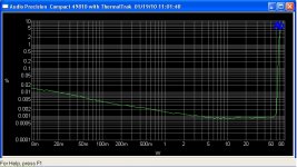
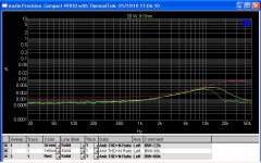
Here are some curves for conventional THD and AP DSP based multitone. The multitone is very fast. It generates all data almost instantly compared to tens of second of sine sweep. I am told that multitone is widely used in production test including the iPods.
Conventional THD vs freq for sine sweep is plotted in dBV scale for ease of comparison with the multitone Distortion measurement.
Attachments
Last edited:
Dear Panson,
Great work and research, which will help all of those who are interested in using those driver chips a lot (including myself!)
One question.
On your website I saw a project with the Thermal Track transistors. You said when used with the the LME49830 no driver stage needed. Did you actually drive the Thermal Tracks direct with with the LME49830? Do you have measurements and/or schematics of this setup? I am very curious.
With kind regards,
Bas
Dear Panson,
Great work and research, which will help all of those who are interested in using those driver chips a lot (including myself!)
One question.
On your website I saw a project with the Thermal Track transistors. You said when used with the the LME49830 no driver stage needed. Did you actually drive the Thermal Tracks direct with with the LME49830? Do you have measurements and/or schematics of this setup? I am very curious.
With kind regards,
Bas
Hi Sebastiaan,
Sorry, that is a typo. We need driver for BJT (ThermalTrak) output devices. I just corrected it.
Thanks!
Panson
I forgot about the documentation:
http://www.unisonus.com/pdf/unisonus_lm_amp.pdf
http://www.unisonus.com/pdf/unisonus_lme49810_amp.pdf
http://www.unisonus.com/pdf/unisonus_lme49811_amp.pdf
P1 should have 2k. I'm not using C6, C7 and CE caps.
Dear Veteran,
Thanks for your contribution.
About the 810 design,
What is the sense of R8 (2,2K) I think you can better ommit R8 because you already determine the bias current with the diodestring and P2.
Other question. What are the bias values for your design?
With kind regards,
Bas
Hi Sebastiaan,
Sorry, that is a typo. We need driver for BJT (ThermalTrak) output devices. I just corrected it.
Thanks!
Panson
Thank you Panson for your fast response!
If I may ask (subjectively). What do you prefer in sound quality. TheThermalTrak's with pre driver, or the STD03's?
Btw. I saw some designs out there on the web with the TT's direct driven by an LME chip. was the TT hFE value around 300? If that is the case it should be possible but with limited current out capacity.
With kind regards,
Bas
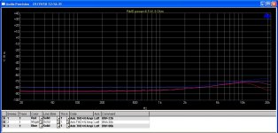
LME49811 amplifier with a compound Darlington output stage and 50VDC rails THD vs Power into an 8 ohm resistive load graph. Can anyone beat this?
Mark / Audioman54
Just posted this on the Class A thread
What is the title of this topic? Would love to find and read it 😉
Thanks.
With kind regargs,
Bas
Thank you Panson for your fast response!
If I may ask (subjectively). What do you prefer in sound quality. TheThermalTrak's with pre driver, or the STD03's?
Btw. I saw some designs out there on the web with the TT's direct driven by an LME chip. was the TT hFE value around 300? If that is the case it should be possible but with limited current out capacity.
With kind regards,
Bas
Hi Bas,
I have not listened to STD03. I personally prefer not using single packaged Darlington devices. The driver and output devices should be thermally isolated.
LME49810 direct drives TT is "okay" if the load light and low power. We should use the min current gain value, 75, and consider reactive load scenarios.
Cheers,
Panson
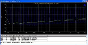
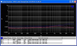
Here is THD vs freq for LME49811 with output stage biased in Class A for 20 W/8 Ohm. THD rise in high freq is almost gone due to vanishing crossover distortion.
The result shown earlier is with two pairs of TT output devices. Here is for four pairs TT. Very promising!!! Better than the earlier result. BW = 22k, 30k 80k from bottom to top.
Attachments

Dear Panson,
One more question. What makes u decide the value of Ccom? Did the amplifier oscillates with a lower value? In my design it worked fine with only 10pF. With this value I kept the high slewrate.
With kind regards,
Bas
One more question. What makes u decide the value of Ccom? Did the amplifier oscillates with a lower value? In my design it worked fine with only 10pF. With this value I kept the high slewrate.
With kind regards,
Bas
Sorry if I'm hijacking this thread... It's my very first post at DiyAudio.
My boards arrived today from Panson and they look impressive! 🙂
Very professional work! - Thanks Panson!
I need some help with the electrolytic capacitors. Can I use 470uF instead of 390 (C6 and C7) and 1000uF instead of 820 (C8 and C9)? I'm having trouble sourcing the BOM values.
Thank you all! 🙂
Regards,
Paulo.
PS: Please forgive my bad English... 🙁
Dear Panson,
One more question. What makes u decide the value of Ccom? Did the amplifier oscillates with a lower value? In my design it worked fine with only 10pF. With this value I kept the high slewrate.
With kind regards,
Bas
Hi Bas,
I also use 10pF in boards without any osc issue, though, 22pF is shown in the BOM. 22pF is a conservative value to start with. 🙂
Cheers,
Panson
Last edited:
Sorry if I'm hijacking this thread... It's my very first post at DiyAudio.
My boards arrived today from Panson and they look impressive! 🙂
Very professional work! - Thanks Panson!
I need some help with the electrolytic capacitors. Can I use 470uF instead of 390 (C6 and C7) and 1000uF instead of 820 (C8 and C9)? I'm having trouble sourcing the BOM values.
Thank you all! 🙂
Regards,
Paulo.
PS: Please forgive my bad English... 🙁
Hi Paulo,
You are welcome! Sure, you can use 470uf and 1000uf to replace those cap as long as the voltage rating is okay for the rails.
Cheers,
Panson
Thanks Panson! 🙂
So, the value of these capacitors is not critical, can I use other values lower or higher? Is there a minimum and a maximum? They´re decloupling caps, right?
What about the wirewound 2W resistors - can they be metal film or metal oxide?
Thanks! 🙂
So, the value of these capacitors is not critical, can I use other values lower or higher? Is there a minimum and a maximum? They´re decloupling caps, right?
What about the wirewound 2W resistors - can they be metal film or metal oxide?
Thanks! 🙂
Thanks Panson! 🙂
So, the value of these capacitors is not critical, can I use other values lower or higher? Is there a minimum and a maximum? They´re decloupling caps, right?
What about the wirewound 2W resistors - can they be metal film or metal oxide?
Thanks! 🙂
Hi Paulo,
Yes, they are rails decoupling caps. In general, larger is better. Use as large as you can as long as the size and voltage rating are okay. However, you still need large enough reservoir caps. These caps just provide a quick discharge path for relatively small amount of energy.
Yes, you can use metal film to replace the 2W wirewound resistors. We can now find inexpensive metal film power resistors.
Cheers,
Panson
Hi Panson,
I'm going to use all resistors metal film. For the decoupling caps, I'll use 100uF 63V for all in the driver board and 1000uF 63V at the power board. Is allright then?
Thanks! 🙂
I'm going to use all resistors metal film. For the decoupling caps, I'll use 100uF 63V for all in the driver board and 1000uF 63V at the power board. Is allright then?
Thanks! 🙂
Hi Panson,
I'm going to use all resistors metal film. For the decoupling caps, I'll use 100uF 63V for all in the driver board and 1000uF 63V at the power board. Is allright then?
Thanks! 🙂
Hi Paulo,
Yes, no problem at all.
Cheers,
Panson
- Home
- Amplifiers
- Chip Amps
- Comparing LME49810, 49830 and 49811