Tom,
I do not know how large your power supply capacitance is, but, have you tried disconnecting the power cord from the source and checking for noise while the amp is running off of the cap charge. It can be real helpful sometimes when trying to isolate whether the noise is design, component, or outside influence.
I have also installed a dedicated earth ground directly buried 10 feet, outside in the yard. No interference from household items.
Tad
I'm running off of an HP 6228B lab power supply and I'm adding 2x1200 uF directly at the amplifier circuit. I doubt the 60 Hz is from the power supply.
~Tom
~Tom
Is'nt a supply noise rather around 120hz ( double rectifying) and an inductive one around 60hz?
I'm running off of an HP 6228B lab power supply and I'm adding 2x1200 uF directly at the amplifier circuit. I doubt the 60 Hz is from the power supply.
~Tom
I test run my amps on a regulated power supply as well, and they can still pick up a.c. from the surrounding environment -- if you have an adjacent device which is drawing a lot of current it will radiate, particularly if the leads are parallel.
You could probably make up some power supply leads out of CAT-5 cables.
This part of the thread should probably be moved or restarted, as the issue is not exclusively related to the LME chips.
Hum, grounding part of this thread has moved
Due to popular demand, I have started a new thread for discussing the hum/hiss issues with LME49810, 811, 830 and LM3886.
Due to popular demand, I have started a new thread for discussing the hum/hiss issues with LME49810, 811, 830 and LM3886.
Is'nt a supply noise rather around 120hz ( double rectifying) and an inductive one around 60hz?
60 Hz (50 Hz in the EU) is typically inductive or capacitive pickup of the mains frequency. I have also seen 60 Hz ripple on a system where one diode in the rectifier was fried.
120 Hz (100 Hz) is normally caused by supply ripple. The ripple has a lot of nasty harmonics in it.
~Tom
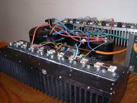
I haven't yet shown here my last lme implementation.
How much power per channel?
I think about 750w/4 capable with 90 volts rails.
Tested at 63 volts for now.
2x 47000uf
High damping factor.
Incredible bass slam.
Tested at 63 volts for now.
2x 47000uf
High damping factor.
Incredible bass slam.
Last edited:
I'm getting some LME49811s from NatSemi as freebie student samples (yay!), and was wondering if someone could recommend a simple schematic and/or PCB to use it. From what I understand, the LME49811 does not require a secondary driver transistor and can be connected to output transistors like the MJL3281/MJL1302 combination directly. Do I have this correct?
I'm getting some LME49811s from NatSemi as freebie student samples (yay!), and was wondering if someone could recommend a simple schematic and/or PCB to use it. From what I understand, the LME49811 does not require a secondary driver transistor and can be connected to output transistors like the MJL3281/MJL1302 combination directly. Do I have this correct?
No, you have it wrong. You will need driver tansistors or use darlington tranistors as shown in the Mational application notes. The darlingtons are driver and output in one package. Sanken is a good source for darlingtons.
The datasheet is a simple schematic which clearly shoes a darlington.
The chip must contain a pre-driver stage.
This making a triple.
The chip must contain a pre-driver stage.
This making a triple.
I'm getting some LME49811s from NatSemi as freebie student samples (yay!), and was wondering if someone could recommend a simple schematic and/or PCB to use it.
I was able to dig out several schematics from this thread by going through from page 1. I'm going to try an LME49810 and LME49811 with the STD03N/STD03P ThermalTrak devices from Sanken. Probably something along these lines.
~Tom
Out of curiosity, how important is it to match transistors for these designs? STD03Ns/STD03Ps aren't cheap, and I'd rather not have to buy a great big pile of them.
I read through the schematics - I'm curious which one works best. I'm a bit confused as to which numbers apply to which amplifier design. I'm also unsure as to exactly how much power I can expect out of it into a given load without it melting. (As you can tell, I'm new to amp design.)
This looks to be what I'm looking for. There's a PCB manufacturing service here in the States that will produce 10 50mm x 50mm PCBs for $30 - just $3 a PCB! There might even be enough room left over on the board to fit an op-amp DC servo of some sort.
I was able to dig out several schematics from this thread by going through from page 1.
I read through the schematics - I'm curious which one works best. I'm a bit confused as to which numbers apply to which amplifier design. I'm also unsure as to exactly how much power I can expect out of it into a given load without it melting. (As you can tell, I'm new to amp design.)
I also have a design for LME49811+STD (or SAP) darlingtons for one year. Its a bit "crowded" but only in 1/8 eurocard (40 x 50 mm). If someone request then I can send the eagle files..
This looks to be what I'm looking for. There's a PCB manufacturing service here in the States that will produce 10 50mm x 50mm PCBs for $30 - just $3 a PCB! There might even be enough room left over on the board to fit an op-amp DC servo of some sort.
if you can fit a 811 into 50x50 you are doing really well.
Adding an 8pin dip will be near a miracle.
Remember the 811 needs a cooler.
1pair of 130 to 150W devices will drive 8r0 to 60W and survive just about any 8ohm speaker.
There are some that would try to get 100W into 8ohm from 1pair, but I prefer 2pair of output devices to achieve that target.
If you used 1pair of 200W to 250W devices you can drive 8ohm to 100W reliably, if you can keep the devices cool.
I'm getting some LME49811s from NatSemi as freebie student samples (yay!), and was wondering if someone could recommend a simple schematic and/or PCB to use it. From what I understand, the LME49811 does not require a secondary driver transistor and can be connected to output transistors like the MJL3281/MJL1302 combination directly. Do I have this correct?
You can use the circuit shown in the data sheet as a starting point. App note 1645 is a good reference.
LME49811 has relatively small output driving capability. You need at least a Darlington output pair or a two-stage EF output. In high-power cases, triple EF is necessary.
I was able to dig out several schematics from this thread by going through from page 1. I'm going to try an LME49810 and LME49811 with the STD03N/STD03P ThermalTrak devices from Sanken. Probably something along these lines.
~Tom
ThermalTrak is an OnSemi trademark, Sanken just calls their units "Darlington Transistor with thermal compensation diode".
Use one trimpot per Sanken pair. That way you won't have to buy a tube.
I was able to dig out several schematics from this thread by going through from page 1. I'm going to try an LME49810 and LME49811 with the STD03N/STD03P ThermalTrak devices from Sanken. Probably something along these lines.
~Tom
There has been quite a bit of discussion about how to take advantage of the thermal compensation diodes in Sanken devices. Sanken recommends a constant 2.5ma (I think it 2.5) current source for them to work correctly. The schematic you referenced doesn't have a constant current source. The national app note uses Sanken Darlingtons (not Std03's) but with a vbe transistor mounted to the heat sink, or better yet, to transistor. The national app note for the Lm4702 has a bit more info as well. The Lm4702 is a two channel version of the Lme49811. The sanken darlingtons in the Lm4702 app note have be superseded by newer Sanken devices. Search the Sanken site for darlingtons.
Ken
Ken
I think about 750w/4 capable with 90 volts rails.
Tested at 63 volts for now.
2x 47000uf
High damping factor.
Incredible bass slam.
What output devices are you using?
I am using lme49810
5 pairs 2sa1295/2sc3264 driven by 2sa1294/2sc2363 such as in the Rotel RB1090.(+ one pair)
5 pairs 2sa1295/2sc3264 driven by 2sa1294/2sc2363 such as in the Rotel RB1090.(+ one pair)
- Home
- Amplifiers
- Chip Amps
- Comparing LME49810, 49830 and 49811