Hmmm,
I've been fighting with Struth's Blameless for two years now. I installed MJL21193/4 in that per his instructions. I wonder if all this time I have just been fighting those outputs. Now I have to try switching those out. Wouldn't it be cool if that was the problem? 😀
I've been fighting with Struth's Blameless for two years now. I installed MJL21193/4 in that per his instructions. I wonder if all this time I have just been fighting those outputs. Now I have to try switching those out. Wouldn't it be cool if that was the problem? 😀
Yes, the main issue - 21193/94 close much slower, than they open. So, as soon, as you try to make them "moving" faster, you get a situation, when both positive and negative shoulders of push-pull are open at the same time, killing them instantly 🙁
Where I have seen 21193/4 actually work well is in EF2's.
Quasi's "power amp under development" - he offered a BJT alternative
to the regular Hexfet design. The two builders swore by the quality of
the amp. Used MJE15033/32 drivers with 220pF B-C shunts(on drivers).
Amp driving it was "slow" (overcompensated blameless) with MJE340/350
VAS. Very basic , strait-forward design ... "NBIP 200" was the name.
PS - this design eventually became the "badger" after a couple years.
OS
Valery
Can You explain me a bit of input stage temperature compensation please (DC offset stability).
I am working on the single ended CFP amp and I prefer to not use DC serveo.
Looks like Q7 and Q8 are heating up in similar way so they are compansating each other ???
Thanks
Peter
Can You explain me a bit of input stage temperature compensation please (DC offset stability).
I am working on the single ended CFP amp and I prefer to not use DC serveo.
Looks like Q7 and Q8 are heating up in similar way so they are compansating each other ???
Thanks
Peter
Valery
Can You explain me a bit of input stage temperature compensation please (DC offset stability).
I am working on the single ended CFP amp and I prefer to not use DC serveo.
Looks like Q7 and Q8 are heating up in similar way so they are compansating each other ???
Thanks
Peter
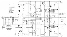
Hi Peter,
OK, the idea is the following. We've got two key stages here - input stage (CFP pair Q2 + Q7) and VAS (Q6, cascoded with Q5). So, for thermal stability of the whole front-end, we need to stabilize two things - input stage and VAS quiescent currents. For that purpose, I use two CCSs, built on Q8 and Q4 respectively, having the same voltage reference - D12 green LED.
LED is a good reference in terms of thermal stability. Thermal stability of the whole front-end actually depends on thermal stability of this LED reference.
VAS bias is set by the voltage drop over R7, but again, the current through R7 is stabilized by the first CCS (Q8, depending on D12 LED reference).
So, as far as D12 voltage reference stays stable, all the other working points also stay very firm and solid. DC offset at the output, when idle, fluctuates within +/-2 mV without the servo in this design.
Hope this helps 🙂
Cheers,
Valery
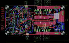
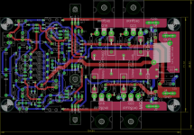
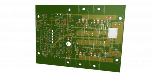
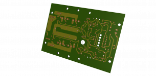
Hi Valery. I Redrawn under CFA-Compact IRFP under Eagle and integrate latest modification from V2 (C14...). It s a 90% your board clone.
Attachments
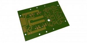
Last edited:
Hi Marc, it looks cool 
Keep us in the loop about your build 😉
P.S. I like the way you placed two gate-protection zeners.
Keep us in the loop about your build 😉
P.S. I like the way you placed two gate-protection zeners.
Last edited:
Hello All,
Just re-checked some values, while soldering the second channel - R27 should be 4.7K
I have experimented to find the optimal value and just "missed" the best one.
Sorry for possible inconvenience 😉
Cheers,
Valery
Just re-checked some values, while soldering the second channel - R27 should be 4.7K
I have experimented to find the optimal value and just "missed" the best one.
Sorry for possible inconvenience 😉
Cheers,
Valery
Hello All,
Just re-checked some values, while soldering the second channel - R27 should be 4.7K
I have experimented to find the optimal value and just "missed" the best one.
Sorry for possible inconvenience 😉
Cheers,
Valery
Hi Valery,
This mod is for both BJT and IRFP version?
Marc
Valery
I think that this amp is just asking for some triode input 😀
When I finish up few projects I will try to atatch some vacum tube at the front of it with feedback connected to the cathode
I think that this amp is just asking for some triode input 😀
When I finish up few projects I will try to atatch some vacum tube at the front of it with feedback connected to the cathode
Some more clarifications : what are the wattage rating for R10/15/16/17/17 and R32/33?
Marc
All those are 1W
Valery
I think that this amp is just asking for some triode input 😀
When I finish up few projects I will try to atatch some vacum tube at the front of it with feedback connected to the cathode
Cool idea, but it's going to take some high-voltage transistors as well...
Hi Valery,
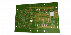
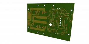
I made some cosmetic changes to spare have more headroom around parts. For this the major change is to swap 0.1u poly from 10mm lead space to 5mm one (100vdc rated too). So there is enough space to place 7k5 1W resistor without overlaping them, i can use silver-mica for pf caps, and use a 2200µf 6v3 nichicon FG for C11 (i have them in stock). I put vent drill under 1W resistors.
I made some cosmetic changes to spare have more headroom around parts. For this the major change is to swap 0.1u poly from 10mm lead space to 5mm one (100vdc rated too). So there is enough space to place 7k5 1W resistor without overlaping them, i can use silver-mica for pf caps, and use a 2200µf 6v3 nichicon FG for C11 (i have them in stock). I put vent drill under 1W resistors.
Attachments
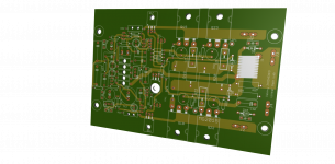

Looks like a real product 🙂
I'm finishing the second channel - will let you know how it goes when ready.
I'm finishing the second channel - will let you know how it goes when ready.
- Status
- Not open for further replies.
- Home
- Amplifiers
- Solid State
- "Compact" VFA