Hi Didiet, very cool and quick as usual 🙂
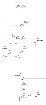
IDSS does not matter for this design - k117 works at 120uA drain (source) current here, set by CCS at the bottom. Any will work fine. THis is one of the advantages of this design - no matching required 😉
Good to know.
I assume, 7.5K NFB resistors are assumed to be placed in a way that every second one is a little bit higher, right? 1W ones are pretty thick.
Yep
With regards to 35-40V I will give you some info later today - need to check couple of parameters...
Cheers,
Valery
Thanks
Didiet, for 35-40V rails, use R4 = 47K
No other changes required. It will give up to around 50 high-quality watts in this case.
Cheers,
Valery
No other changes required. It will give up to around 50 high-quality watts in this case.
Cheers,
Valery
Valery, since 2SK117 are hard to come by, can you please show the changes (cascode) required in the CFA using 2SK170BL or even BF862. Of course, this will also double up as an IPS for the Slewmaster OPS. Thanks a ton for infusing "life" into the SS forum at a pace most of us cannot even come close to.
The BF862 would be an interesting choice. A surface mount version of this IPS would be very interesting
Valery, since 2SK117 are hard to come by, can you please show the changes (cascode) required in the CFA using 2SK170BL or even BF862. Of course, this will also double up as an IPS for the Slewmaster OPS. Thanks a ton for infusing "life" into the SS forum at a pace most of us cannot even come close to.
Hi Samuel, thank you for the feedback 🙂
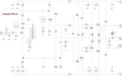
Attached is version of the input section with cascode, allowing low Vds jfets.
2SK170 will work fine here. No influence on performance, compensation, etc.
You can also use BC546 for the cascode (just for unification).
I don't have the model for BF862, however BF861 did not work in simulation. I don't know why as yet - need to think about it. I will let you know as soon as I understand the reasons 😉
Cheers,
Valery
Attachments
The BF862 would be an interesting choice. A surface mount version of this IPS would be very interesting
Hi Carl, agree - SMD version would be very cool
 I will try to investigate what's going on with BFxxx here 😉
Cheers,
Valery
!!! Important update !!! Stability correction!
During long-term testing, possible issues were discovered due to the input CFP potential instability. It is completely cured by adding C14 (68pF) capacitor between the gate of Q2 and the base of Q7. It has to be added to all versions, including the one with the cascode.
I have also slightly optimized the values of C9 and R9 (33pF and 56R respectively). Now everything is perfect 🙂
Cheers,
Valery
P.S. Updated schematic is attached.
Attachments
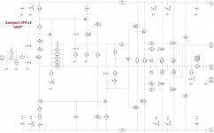
IRFP (Hex-FET) version - I like it even more...
Of course I could not stand from testing the MOSFET version of this one 🙂
IRFP240/9240 are rugged devices, working perfectly with this front-end.
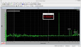
See the distortion spectrums (THD, IMD) - note the profile and level harmonics (2W output power). Due to rather wide open-loop bandwidth, THD grows slowly with frequency increase, ensuring excellent performance at highs.
Quiescent current is 62.5mA per output pair.
Sounds great, even at low volumes - no sign of "flattening". Requires 2-3 minutes after power-on to warm-up for maximum performance.
Have fun 😉
Valery
P.S. PCB is fully compatible, as GDS of Hex-FETs are in the same order as BCE of the BJTs
Of course I could not stand from testing the MOSFET version of this one 🙂
IRFP240/9240 are rugged devices, working perfectly with this front-end.
See the distortion spectrums (THD, IMD) - note the profile and level harmonics (2W output power). Due to rather wide open-loop bandwidth, THD grows slowly with frequency increase, ensuring excellent performance at highs.
Quiescent current is 62.5mA per output pair.
Sounds great, even at low volumes - no sign of "flattening". Requires 2-3 minutes after power-on to warm-up for maximum performance.
Have fun 😉
Valery
P.S. PCB is fully compatible, as GDS of Hex-FETs are in the same order as BCE of the BJTs
Attachments


Last edited:

Hi Valery,
What are the coil spe. (sizes) you are using on picture?
Marc
Hi Marc,
It's 12 turns of 1.2mm copper wire (Wellemann), wrapped around 8mm plastic pen 🙂
Giving around 1.5-2 uH inductance - perfect for the purpose.
Cheers,
Valery
Hi Marc,
It's 12 turns of 1.2mm copper wire (Wellemann), wrapped around 8mm plastic pen 🙂
Giving around 1.5-2 uH inductance - perfect for the purpose.
Cheers,
Valery
Perfect Thanks Valery.
Is there an audible difference in sound between BJT and Mosfet output devices in this amp?Of course I could not stand from testing the MOSFET version of this one 🙂
IRFP240/9240 are rugged devices, working perfectly with this front-end.
See the distortion spectrums (THD, IMD) - note the profile and level harmonics (2W output power). Due to rather wide open-loop bandwidth, THD grows slowly with frequency increase, ensuring excellent performance at highs.
Quiescent current is 62.5mA per output pair.
Sounds great, even at low volumes - no sign of "flattening". Requires 2-3 minutes after power-on to warm-up for maximum performance.
Have fun 😉
Valery
P.S. PCB is fully compatible, as GDS of Hex-FETs are in the same order as BCE of the BJTs
Hi Jeff,
Difficult to compare at the moment - the BJT version is still sort of "damaged" - that's the way I have found there was a problem with sporadic oscillations (150-200MHz), caused by input CFP pair, happening at higher output levels 🙂 All 4 output transistors were killed instantly (over-current sensor was not connected at that time).
HexFet version is much more rugged, so it allowed me a number of experiments until I clearly understood that the cause is the input pair and cured it with additional cap. HexFETs were tripping the protection, but did not break - very tough devices.
I will let you know my impressions as soon as I repair the BJT one and compare them A-B. So far, the FET one sounds excellent, impression is close to CFA-CFPx2 in terms of very clear, accented highs, although it also needs some closer comparison - can't say more than that at the moment.
Cheers,
Valery
I've got my CFA-CFPx2 BJT version assembled but haven't had a chance to compare it either.Hi Jeff,
Difficult to compare at the moment - the BJT version is still sort of "damaged" - that's the way I have found there was a problem with sporadic oscillations (150-200MHz), caused by input CFP pair, happening at higher output levels 🙂 All 4 output transistors were killed instantly (over-current sensor was not connected at that time).
HexFet version is much more rugged, so it allowed me a number of experiments until I clearly understood that the cause is the input pair and cured it with additional cap. HexFETs were tripping the protection, but did not break - very tough devices.
I will let you know my impressions as soon as I repair the BJT one and compare them A-B. So far, the FET one sounds excellent, impression is close to CFA-CFPx2 in terms of very clear, accented highs, although it also needs some closer comparison - can't say more than that at the moment.
Cheers,
Valery
Hi Valery,
Did you simulate Darlingtons in place of Mosfets? Is this a direct replacement or some adjustment is going to be necessary like reducing 220R's at gates (bases)?
Thanks.
Did you simulate Darlingtons in place of Mosfets? Is this a direct replacement or some adjustment is going to be necessary like reducing 220R's at gates (bases)?
Thanks.
Hi Valery,
Did you simulate Darlingtons in place of Mosfets? Is this a direct replacement or some adjustment is going to be necessary like reducing 220R's at gates (bases)?
Thanks.
Hi Terranigma,
You're right, of course the biasing, pre-driver/driver elements, base/gate stoppers are adapted for each type of output devices.
Attached are appropriate schematics - BJT and MosFET ones respectively (use "arrows" button at the bottom left corner for full size image.).
Cheers,
Valery
Attachments


Hi Valery,
Are still using MJL21193/94 in a Slewmaster OPS? Did you get them to be stable? I may have given up on those too soon. I wouldn't mind trying again.
Thanks, Terry
Are still using MJL21193/94 in a Slewmaster OPS? Did you get them to be stable? I may have given up on those too soon. I wouldn't mind trying again.
Thanks, Terry
Hi Terry, actually now, I did not use them in Slewmaster since those times as well. njw3281/njw1302 are better anyway, just because they are faster. MJL21193/94 are ok for "slower", heavily compensated designs...
21193/94 Cob is a little higher(500pf) , Cib( 7000pF junction capacitance)
is 10X magnitude of a 0302/0281. Bad as a Hexfet Ciss (worse).
0281 Cib is <800pF , Cob 300-400pF.
The old 21193/4 forms a nifty little oscillator with that much C in an EF3.
Heavily shunting from B-C on the drivers might alleviate the problem ,
but you have a slower driver stage to match an already slow OP stage..
Just use fast OP's and save your 21193/4's for regulators or motors 😀.
Proper device for proper app ! 🙂
OS
- Status
- Not open for further replies.
- Home
- Amplifiers
- Solid State
- "Compact" VFA