PDF please😉
I have some 2sk146,can i use them?
Mary Cristmas
Unfortunately, 2sk146 have got too low Vgds for this design.
2sk389 can be used here (although it will require some minor layout amendment).
Merry Christmas!

Bf862
Also out of SOA. Vds / Vdg = 20V max.
We need at least 50V for these designs.
Again, it's possible to add a common-base cascade to lower the drain voltage, however it requires some additional parts (although some LEDs will go). I tried to keep it simple - even at the price of limited choice of transistors...
Cheers,
Valery
Cascode, and you can lower the the buttom railvoltage with a resistor prior to the CCS.
A cascode above the Jfet seems to improve the rhythm of the amplifier
A cascode above the Jfet seems to improve the rhythm of the amplifier
Hi Valery
Have a preference for 2SK117 grade
Did you seen anyobjection to the use of faster ouput devices as NJW1302/3281?
Marc
Have a preference for 2SK117 grade
Did you seen anyobjection to the use of faster ouput devices as NJW1302/3281?
Marc
Last edited:
Hi Richard, most likely, the single-ended one will have a certain slew asymmetry, not too high though. Difficult to see in simulation, but I will measure it if I appear to prototype this one.
Cheers,
Valery
Cheers,
Valery
Hi Valery
Have a preference for 2SK117 grade
Did you seen anyobjection to the use of faster ouput devices as NJW1302/3281?
Marc
Hi Mark,
No preference for the grade (the ones I've got are marked as just 2SK117).
Faster output devices - even better.
Cheers,
Valery
Hi Mark,
No preference for the grade (the ones I've got are marked as just 2SK117).
Faster output devices - even better.
Cheers,
Valery
Thanks for reply Valery
Marc
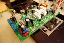
Compact CFA is prototyped and tested!
Hi All,
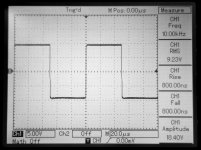
Tested the CFA one today. Pretty cool. Stable, low distortion, fast, symmetric slew and clipping. No clipping artifacts. All measurements are done at 8R load except clipping test (100R). DC at the output stays within a couple of mV.
Great sound. Somehow, bass here seems to sound a bit "softer" - in a positive sense - that the other CFAs I tested before. Staying very detailed and natural at the mids and highs.
PSU voltage is +/-52V DC, non-regulated (as usual). Dead quiet with no signal.
It's fast enough even with the slow output transistors. However - be careful. Input signal at the frequencies above 500KHz may kill the OPS if it's not fast enough (current shoot-through across the output pairs as they close slower then they open). With faster devices, including most of the MOSFETs, this is not a problem.
Cheers,
Valery
Hi All,
Tested the CFA one today. Pretty cool. Stable, low distortion, fast, symmetric slew and clipping. No clipping artifacts. All measurements are done at 8R load except clipping test (100R). DC at the output stays within a couple of mV.
Great sound. Somehow, bass here seems to sound a bit "softer" - in a positive sense - that the other CFAs I tested before. Staying very detailed and natural at the mids and highs.
PSU voltage is +/-52V DC, non-regulated (as usual). Dead quiet with no signal.
It's fast enough even with the slow output transistors. However - be careful. Input signal at the frequencies above 500KHz may kill the OPS if it's not fast enough (current shoot-through across the output pairs as they close slower then they open). With faster devices, including most of the MOSFETs, this is not a problem.
Cheers,
Valery
Attachments
-
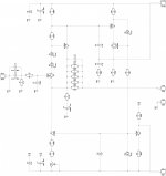
 @00-Compact-CFA-Sch.jpg519.1 KB · Views: 470
 -
 @05-DSC03526.JPG301.4 KB · Views: 159
 -
 @05-DSC03524.JPG269.6 KB · Views: 139
 -
 @05-DSC03523.JPG290.7 KB · Views: 117
 -
 @05-DSC03522.JPG280.5 KB · Views: 142
 -
 @03IMD-14-15K-01.jpg201.7 KB · Views: 150
 -
 @02THD-20K-01.jpg194.9 KB · Views: 364
 -
 @02THD-01K-01.jpg200.3 KB · Views: 386
 -
 @00-DSC03530.JPG300.5 KB · Views: 409
 -
 @00-DSC03529.JPG343.7 KB · Views: 458
Nice , Val.
Hey.. make a standardized IPS out of it.
PS - with CCS / cascoded simple VAS , will work VERY well with my EF3.
And just 1 Jfet - no matching.
It looks like perfect alternative to the 7 device bootstrap VFA.
Do I see 2 pole compensation at VAS ??
OS
Hey.. make a standardized IPS out of it.
PS - with CCS / cascoded simple VAS , will work VERY well with my EF3.
And just 1 Jfet - no matching.
It looks like perfect alternative to the 7 device bootstrap VFA.
Do I see 2 pole compensation at VAS ??
OS
Dear Valery,
Which program are you using to draw schematics and for PCB layout?
--gannaji
Hi Gannaji, I use Diptrace for schematics and PCB design (they are linked, so that changes in schematic can be automatically reflected on PCB).
Cheers,
Valery
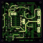
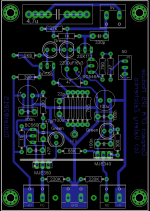
Slewmaster-compatible IPS module
Good idea to make a "standardized", Slewmaster-compatible IPS. Here it is 🙂
Being rather simple, it easily fits 3"x3" board. Output plugs layout appears a bit "messy" as it was initially designed with "mirrored" rails. I'm sure, somebody can make a better single-layer layout 😛
Heatsink is not required at around 5mA VAS current, however, if somebody will like to drive the Lateral FETs directly from here, the VAS cirrent will have to be increased to some 15mA - in this case the heatsink will be needed.
Compensation is actually Miller (plus the lead cap in parallel with GNFB). C8, R11 is just an RC filter, correcting the frequency response above 30MHz and improving the gain margin for about 3db 😀 ULGF is set to 2MHz, however, the point, where the phase flips over 180 degrees is at around 40MHz - that's where the falling gain reaches -19db.
Frequency response is limited to around 500KHz by the input filter. With C3=100pF it will go above 1MHz, staying stable, but again - at such bandwidth, if the OPS devices are not fast enough, they will be killed by the rail-to-rail current shoot-through.
MT-200 Sankens will work well here, BTW...
You're right, no matching required here. Overall simplicity/performance rating appears huge 😉
Cheers,
Valery
Nice , Val.
Hey.. make a standardized IPS out of it.
PS - with CCS / cascoded simple VAS , will work VERY well with my EF3.
And just 1 Jfet - no matching.
It looks like perfect alternative to the 7 device bootstrap VFA.
Do I see 2 pole compensation at VAS ??
OS
Good idea to make a "standardized", Slewmaster-compatible IPS. Here it is 🙂
Being rather simple, it easily fits 3"x3" board. Output plugs layout appears a bit "messy" as it was initially designed with "mirrored" rails. I'm sure, somebody can make a better single-layer layout 😛
Heatsink is not required at around 5mA VAS current, however, if somebody will like to drive the Lateral FETs directly from here, the VAS cirrent will have to be increased to some 15mA - in this case the heatsink will be needed.
Compensation is actually Miller (plus the lead cap in parallel with GNFB). C8, R11 is just an RC filter, correcting the frequency response above 30MHz and improving the gain margin for about 3db 😀 ULGF is set to 2MHz, however, the point, where the phase flips over 180 degrees is at around 40MHz - that's where the falling gain reaches -19db.
Frequency response is limited to around 500KHz by the input filter. With C3=100pF it will go above 1MHz, staying stable, but again - at such bandwidth, if the OPS devices are not fast enough, they will be killed by the rail-to-rail current shoot-through.
MT-200 Sankens will work well here, BTW...
You're right, no matching required here. Overall simplicity/performance rating appears huge 😉
Cheers,
Valery
Attachments
Valery
Very nice and simple circuit, I have to press ''Like'' button a good few times but It hasn't been implemented in forum mechanism yet 😀
The simpe circuits have a lot of positive ''vibrations'' passing threw the cables to the speakers so they sounds lovley - especially with single transistor input.
Very nice and simple circuit, I have to press ''Like'' button a good few times but It hasn't been implemented in forum mechanism yet 😀
The simpe circuits have a lot of positive ''vibrations'' passing threw the cables to the speakers so they sounds lovley - especially with single transistor input.
Valery
Very nice and simple circuit, I have to press ''Like'' button a good few times but It hasn't been implemented in forum mechanism yet 😀
The simpe circuits have a lot of positive ''vibrations'' passing threw the cables to the speakers so they sounds lovley - especially with single transistor input.
Thank you Peter 😉
Hi Gannaji, I use Diptrace for schematics and PCB design (they are linked, so that changes in schematic can be automatically reflected on PCB).
Cheers,
Valery
Can you kindly post the .dch and .dip files for this project? (For the simple CFA). I am using Diptrace and I would like to experiment more.
Last edited:
No problem, can you please drop your e-mail to my private box - I don't like keeping the source files openly accessible 😉
Hi Didiet, very cool and quick as usual 🙂
IDSS does not matter for this design - k117 works at 120uA drain (source) current here, set by CCS at the bottom. Any will work fine. THis is one of the advantages of this design - no matching required 😉
I assume, 7.5K NFB resistors are assumed to be placed in a way that every second one is a little bit higher, right? 1W ones are pretty thick.
With regards to 35-40V I will give you some info later today - need to check couple of parameters...
Cheers,
Valery
- Status
- Not open for further replies.
- Home
- Amplifiers
- Solid State
- "Compact" VFA