And the second question. You state this idea of taming resonances with DSP. I also had this idea when I built my current main speakers. My intuition said, that a passive crossover sucking out the resonance peaks is no different from IIR DSP filters. The extra energy is not burned up in the resistor, it goes to the amp. The resistor in the LRC is just to set the level at which signal goes through it versus the speaker. Since IIR filters behave like passive components, I thought the the end result would be pretty much the same in the amp and speaker perspective. Do you have facts about this? You see, I usually get best results when I do the exact opposite of my intuition, so I removed these DSP filters and went on with my life.Since DSP is in the signal chain, the spectral balance can be tailored for a given listening position in a given room. The basic architecture will have a lot of flexibility, and it should be possible to integrate different midrange/tweeters, including a waveguide option if that is what you want. The passive crossover needs to manage the magnitude and phase through the crossover region, and suppress the midrange cone breakup resonance. But all of the baffle step, bass EQ, spectral balance, in-band resonance suppression, and voicing is handled by DSP.
One last thing. The title says "compact 3-way," and having built a 2-way with 10" woofer, I consider your project a medium size speaker or a big speaker for stand-mount standards. Did you ever consider a really small 3-way speaker, like one with a 5-6" woofer (that would be something I'd like to try in the future)? Or would that fall behind from your goals? I've read the discussion about going from 8" to 10", but my 10" 2-way is high-passed at 60 Hz just so I can reason a bigger bassleg to my wife... Just saying that if you don't expect a full-range performance out of a "compact" speaker, you might get good enough performance anyway and adding a woofer in separate enclosure could be more reasonable than doubling the speaker count. I did that and also Troels did, if you look at the link. Of course that would need more planning in the DSP and amount of available channels/ways. It's not impossible to add another miniDSP 2x4HD, but it would certainly add costs.
Taming a driver resonance with DSP is appropriate, it does work to some extent. However, a passive filter which changes the impedance can do a better job. In my case, I will be suppressing the 10k midrange driver resonance with the passive filter.And the second question. You state this idea of taming resonances with DSP.
Your first question about cabinet shape... yes, I did consider a trapezoid shape, but I think this is a more complicated construction compared to an orthogonal box. One of the goals is to design something which is easily replicable, so I can make more of them, or someone else can easily build.
The word "compact" is relative, as is "low cost". What is "low cost compact" to me might be "pricey and large" to someone else. However, this is a full range design, with an F3 of 36 Hz and an F6 of 28 Hz. It is 25 liters, which is small for a 10" woofer system with this much bass extension. Most speakers with bass performance extending this low are at least 40 liters.One last thing. The title says "compact 3-way," and having built a 2-way with 10" woofer, I consider your project a medium size speaker or a big speaker for stand-mount standards. Did you ever consider a really small 3-way speaker, like one with a 5-6" woofer (that would be something I'd like to try in the future)? Or would that fall behind from your goals?
It looks large in my sketch, because it is tall and wide, but it is very shallow, just 222 mm deep. The height is 648 mm, and if I reduced the space between the 3 drivers to 0 (touching), the height would be 578 mm. There is only 70 mm of extra vertical baffle space in this speaker. In terms of width, the bass driver is 272 mm diameter, and the cabinet width is 292 mm... leaving just 10 mm edge clearance per side... so from the standpoint of width and height, the speaker could not really be much smaller.
If a person wanted to build a very small 3-way speaker, I would recommend the @wolf_teeth design
https://www.diyaudio.com/community/...-3-ways-ive-built-or-seen.392609/post-7184081

I can do 96k with steps on scarlett 2i2 2e gen. Did not see much difference in results though.I followed that manual. I had to adjust the "audio device setup" control panel since it seems to require a different set of values than ARTA. I also found that with my laptop and my motu audio interface, STEPS requires a 48k sampling rate, while in Arta I can use a 96k sampling rate. When using a 96k sampling rate, STEPs would give me a buffer overflow error and crash Windows. The overall "look and feel" is very similar to Arta, and it is obvious they share a common heritage. I am actually a little surprised I got it to work without much problem... Normally I am barely literate when it comes to PC based audio.
Regarding the smoothing... I was looking for a way to smooth the %distortion plots, and I did not find a way to do it... but I stumbled on an option to smooth the recorded signal at 1/1, 1/2, or 1/3 octave. I tried this, and got the result I wanted... and then thinking about it, it all made sense.
I have been doing some simulations with the latest prototype data. This data was collected from a XPS foam board prototype baffle which is representative of the midrange and tweeter baffle. I describe it in post #314 https://www.diyaudio.com/community/threads/compact-low-cost-active-3-way-speaker.402812/post-7471898
The data I have collected from this prototype is high resolution data because it is highly representative of the baffle shape I intend to use in the final speaker. I needed this kind of data because I cannot simulate with enough accuracy the small and subtle variations in power and ER response that arise from driver positioning on the baffle. I need to define the location of the midrange, which will fix the center-to-center spacing between the mid and tweeter. I need to do this before I can begin constructing the cabinet.
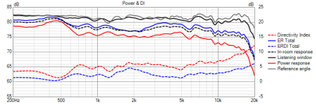
The XPS foam box has some limitations. It has a broad resonance from 350 – 700 Hz. For example, at 90 degrees horizontal, the 500 Hz radiation is equal to the on-axis 500 Hz radiation. This is great enough to screw up the Power and DI curves in this range from 350 – 700 Hz. So when looking at the Power and DI plots, we have to ignore this region.
For the purposes of defining the mid/tweeter spacing, I created a simulation using a combination of active and passive elements. This more or less mimics the design architecture of the finished speaker. With this set of measurements, there are 2 crossover designs which would seem to work. I want to stress that at this point I am not designing the crossover and DSP filters. I am simply studying the effects of CTC spacing with two plausible crossovers.
The first design uses a 3rd order acoustic slope on the mid with a series notch filter. The second one uses a 4th order topology on the mid, which results in a 5th order acoustic rolloff, and no need for a notch filter.
In both crossover designs, the tweeter high pass is very similar: a 3rd order topology which results in a rolloff which starts as approximately 3rd order and transitions to approximately 4th order.

Here is the first design, with a CTC spacing of 165 mm, which leaves a 37mm space between the mid and tweeter.

Here is the first design with a CTC spacing of 135 mm, which leaves just a small 7mm space between the mid and tweeter.

The data I have collected from this prototype is high resolution data because it is highly representative of the baffle shape I intend to use in the final speaker. I needed this kind of data because I cannot simulate with enough accuracy the small and subtle variations in power and ER response that arise from driver positioning on the baffle. I need to define the location of the midrange, which will fix the center-to-center spacing between the mid and tweeter. I need to do this before I can begin constructing the cabinet.
The XPS foam box has some limitations. It has a broad resonance from 350 – 700 Hz. For example, at 90 degrees horizontal, the 500 Hz radiation is equal to the on-axis 500 Hz radiation. This is great enough to screw up the Power and DI curves in this range from 350 – 700 Hz. So when looking at the Power and DI plots, we have to ignore this region.
For the purposes of defining the mid/tweeter spacing, I created a simulation using a combination of active and passive elements. This more or less mimics the design architecture of the finished speaker. With this set of measurements, there are 2 crossover designs which would seem to work. I want to stress that at this point I am not designing the crossover and DSP filters. I am simply studying the effects of CTC spacing with two plausible crossovers.
The first design uses a 3rd order acoustic slope on the mid with a series notch filter. The second one uses a 4th order topology on the mid, which results in a 5th order acoustic rolloff, and no need for a notch filter.
In both crossover designs, the tweeter high pass is very similar: a 3rd order topology which results in a rolloff which starts as approximately 3rd order and transitions to approximately 4th order.
Here is the first design, with a CTC spacing of 165 mm, which leaves a 37mm space between the mid and tweeter.
Here is the first design with a CTC spacing of 135 mm, which leaves just a small 7mm space between the mid and tweeter.
… And here is the second crossover design with a spacing of 165 mm

Now the second crossover design with a spacing of 135 mm

The effect of CTC spacing is not as large as I expected. In some other designs, mid/tweeter CTC spacing was an important aspect of getting the DI curve, the PIR curve, and on-axis curve all optimized. In this case, shrinking the CTC spacing from 165 mm (the biggest possible) to 135 (almost the smallest possible) makes little difference. Another surprise is that with these prototype crossovers, the Fc is lower than I expected. I originally expected the crossover frequency to be around 2.5k, and at that frequency a 165mm CTC is equivalent to 1.2xWL. However, when optimizing these prototype filters, an Fc of about 1.8k resulted in the best optimized combination of on-axis, power response, and PIR response.
My opinion is that the 165 mm spacing has a small performance advantage over the 135 mm spacing, but the 135 mm spacing has a small aesthetic advantage.
j.
Now the second crossover design with a spacing of 135 mm
The effect of CTC spacing is not as large as I expected. In some other designs, mid/tweeter CTC spacing was an important aspect of getting the DI curve, the PIR curve, and on-axis curve all optimized. In this case, shrinking the CTC spacing from 165 mm (the biggest possible) to 135 (almost the smallest possible) makes little difference. Another surprise is that with these prototype crossovers, the Fc is lower than I expected. I originally expected the crossover frequency to be around 2.5k, and at that frequency a 165mm CTC is equivalent to 1.2xWL. However, when optimizing these prototype filters, an Fc of about 1.8k resulted in the best optimized combination of on-axis, power response, and PIR response.
My opinion is that the 165 mm spacing has a small performance advantage over the 135 mm spacing, but the 135 mm spacing has a small aesthetic advantage.
j.
It doesn't surprise me that 30mm doesn't make a lot of difference at 1.8khz. I'm curious about how you ended up at 1.8khz. Do you run some optimizer in Vcad? If you forced an Fc of 2.5khz, how do the two differ?
Here are the verticals for prototype filter design 1Could you also show the vertical directivity plots of the 165mm vs 135mm designs?
165mm spacing first
135 mm spacing second
Yes, I have been using the optimizer more often now that I have become more familiar with it. In general, the DI performance gets better as the crossover goes lower, and obviously the tweeter is the limiting factor here. In the real world, 1.8k might be too low for this tweeter in this application.It doesn't surprise me that 30mm doesn't make a lot of difference at 1.8khz. I'm curious about how you ended up at 1.8khz. Do you run some optimizer in Vcad?
I did some sims with the crossover in the 2.5k range. I will go dig them up and see how CTC spacing impacts performance.
Surprisingly small difference in verticals, but you knew this based on previous project!
Here is a comparison at 2.3k... Still not much difference. This is actually a more realistic comparison, as I expect the final crossover to be above 2k.If you forced an Fc of 2.5khz, how do the two differ?
First 165 mm CTC
And next is 135 mm CTC
And of course we still see the big bump in power response at 500 Hz which is a test error coming from the XPS foam box resonance.
j.
First is 165 mm spacingso break out the ceiling, floor, and vertical reflections in the Power & DI chart to see what's it doing there.
and now here is 135 mm spacing
@augerpro , @tktran303 - - I appreciate any thoughts and observations you have... j.
From the figures above, the ERDI seems better with the 165mm spacing compared to the 135mm spacing, probably as expected..
The impact of floor reflection seems milder for 165mm spacing and impact of ceiling reflection is about the same in both configurations.
So the floor reflection maybe less problematic (if it is even a problem at all to begin with) with 165mm spacing, by a small amount compared to 135mm?
How it will all sound like in the real world, I have no idea at all 😀
Yes, it was a good thought to break out the vertical components of power and ER. The wider spacing does look a bit better.
If you want smooth out the vertical DI bump, set the CTC to about 1 wavelength, make the crossover asymmetric by pushing the woofer crossover higher and delay the woofer a little to put it out of phase. I don't know if I think this is a better compromise though...
Have any of you folks tried compared the stepped sine distortion measurement function in the REW RTA module to STEPS? I should think that they would give comparable results, without the limitations you are seeing in the swept sine measurements.This is a strength of STEPS.
When displaying distortion REW displays the fundamental with a smoothing level of 1/24th octave. It is fixed at smoothing interval and cannot be changed, AFAIK.
One really needs click to various viewing options eg. Hx and fundamental as absolute SPL and analyse it further, like how Jim has kindly demonstrated, to see why distortion percentage might appear to have ripples.
@JohnPM
In the Distortion graph; Would it be possible to have the frequency response smoothed at 1/12 octaves or 1/6 or 1/3 octaves? I find that 1/24 is great for midrange/treble frequencies, but below the Schröeder frequency it does cause fluctuations is apparent bass distortion
Bill
- Home
- Loudspeakers
- Multi-Way
- Compact, low cost, active 3-way speaker