Hello, I am new here and I am trying to bypass the lamp on a Sanyo PLV Z2. The projector lamp ballast comes out with only two contacts/wires so I don't know how it detects the bulb. I am planning to convert this to LED using a Cree XML.
I think the photos and notes I posted above should help you keep the projector up and running with the lamp out
Bohanna 🙂
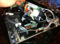
So, I'm having some trouble identifying which part of my projector is the ballast and which wires are going to it. Based on the schematics it looks like the ballast is somewhere in here.
The 2 thick gray wires go around the projector to the bulb. The three white wires go from one small board to the other.
Any guesses on which part of this is the ballast? Or should I be looking somewhere else?
The 2 thick gray wires go around the projector to the bulb. The three white wires go from one small board to the other.
Any guesses on which part of this is the ballast? Or should I be looking somewhere else?
Attachments
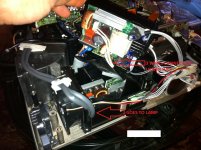
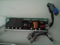
The Ballast is the board that has the two large wires that go to the lamp. I beleive that the connector you are looking for is the one with the clear plastic see through jacket located Just under the "IR" letters in the 3 wires connect red text on your picture.
Bohanna
Bohanna
Ok, that was my guess too, one of the 3 white wires then, specifically the one with the clear jacket? And I just run this wire to ground? I am going to put my mm on there tonight and check for the 3.5v. Although the wiring diagram seems to indicate there is a 5v, but not a 3.5v.
http://www.diyaudio.com/forums/diy-projectors/206387-epson-emp-74-led-mod.html
here is my post for epson emp-74 lamp hack with led mod
here is my post for epson emp-74 lamp hack with led mod
hi, i have a toshiba tdp tw90
i did the steps exactly and none of the wires worked.
is there anything i need to do differently for a toshiba
i did the steps exactly and none of the wires worked.
is there anything i need to do differently for a toshiba
toshiba tlp s10
hi
I have this projector and need ballest voltage in and outgoing information , from how many voltage are coming to lamp balest adapter and then how many voltage are going to bulb . i want to modification with XENON HID KIT SATZ H1 6000k
i have modification the lamp reflector .
hi
I have this projector and need ballest voltage in and outgoing information , from how many voltage are coming to lamp balest adapter and then how many voltage are going to bulb . i want to modification with XENON HID KIT SATZ H1 6000k
i have modification the lamp reflector .
My dear, I m Malik Abdul Rauf
I need to bypasse the ballast of my Sanyo Porjector Sanyo PLC-EF10EA -00 for repalaceing the 440W MH lamp with LED COB Chip Light Source
I appriciate if any one Help me in this regard,
malikrauf22@gmail.com
malikrauf22@yahoo.com
Hoping All the Best
Malik Abdul Rauf
Malik Projectors
Last edited:
http://www.diyaudio.com/forums/diy-...ercial-projector-ballast-bypass-guide-10.html
check out from about post 92 on and read the notes,,,, Even though you have a bigger model You should have the same little jumper cable on your sanyo. Good luck with the LED. Make sure you are going to use the cree's . also look into "electrodacus" on you tube
He gives a great explanation of how the LEDs need to be a tight beam to work. You may also want to consider seperate LED'd for each of the three LCD panels to get more light out of the projector.
Good luck
http://www.youtube.com/watch?v=v1pkCavwGgA
Bohanna
Last edited:
I have a Benq mp620c and i want to by pass lamp check because no leds are on. The connector from ballast to MB have 5 wire. I try to put each wire to gnd but nothing. Please help me.
Sorry for my English.
Sorry for my English.
i have a benq mp620c and i want to bypass lamp check because no leds and buttons are on . The connector from ballast to motherboard have 5 wires. I try to gnd each wire but nothing. Please help me.
Sorry for my English.
Sorry for my English.
Has anyone had to defeat a thermal sensor? I am working with a dlp projector and I have this last sensor board to fool. I tried putting it next to different heat sources to get it to work and read the ohms of resistance at the right temp but so far I have not had any luck.
Flickr: CGIAnimated's Photostream
At room temp I measure 11 ohms of resistance and with the sensor on a cup of hot coffee, then near a candle. I got it down to 5 ohms but I could not get the projector to power up properly without the red temp light coming on.
there are 4 wires and Im not sure how i should go about splicing in a resistor to simulate the right temp.
 Post removed as this was a non isolated PSU and as such contravenes the forum rules.
Working on this type of PSU without the required knowledge can be lethal... to you and others.
[img=http://img692.imageshack.us/img692/4561/yee5iy1tr6.jpg]
ok then PSU covered
HITATCHI pj-TX100
99% sure this is the wire to earth
PSU was sent for electrical layout
ok then PSU covered
HITATCHI pj-TX100
99% sure this is the wire to earth
PSU was sent for electrical layout
Hey,
I try to bypass the ballast on the LP820. What I did so far:
1. Projector shutted down after 30 Seconds with message "retrying"
2. I bridged grey and black on the cable that comes from the mainboard and goes to the ballast, the projector now stays on without searching and i get a picture from my input device, but still after 30 seconds the lamp goes off, no error on the display
3. I tried to bridge other colors without luck
What can I do? Is ballast removal an option?
Thanks a lot for the help!
best regards,
Andreas
P.S.: Service Manual infocus LP815-820_ServiceManual
My lamp control board is an OSRAM that uses UART communication with the mainboard. It is a 5-pin. Some of you had 5-pins as well. My crude understanding is 3-pins check "Logic levels." 5-pins, mine anyway, are UART communication.
I excerpted a page from the pdf and emailed it to a guy from youtube that seemed to know his stuff---He basically said it can't be done---I don't buy that. Im holding/looking at my control board with the 3 optocoupler's (Photo-transistors), 2-pin power, 5-pin comm and I'm thinking crazyguy's method is on the right track.
here's THE PIC WITH PINOUT! Someone PLEASE follow up.
http://i1287.photobucket.com/albums/a621/melgibson377/osrm_zps90500982.jpg
- Home
- General Interest
- Everything Else
- The Moving Image
- DIY Projectors
- Commercial Projector Ballast Bypass Guide