Pt-ar100
Hola, señores. Tengo 3 proyectores pt-ar100 que usa un controlador de balastra ushio mpl3401 he intentado engañar la placa, sin ningún éxito. Ayuda gracias
Hola, señores. Tengo 3 proyectores pt-ar100 que usa un controlador de balastra ushio mpl3401 he intentado engañar la placa, sin ningún éxito. Ayuda gracias

English only please.
Hello, Gentlemen. I have 3 PT-ar100 projectors that uses a ballast Ushio controller mpl3401 I've tried to cheat the plaque without any success. Help thanks
Pt-ar100
Hello Sirs. I have 3 pt-ar100 projectors that uses a ushio mpl3401 ballaster controller that tried to cheat the board, without any success. Help, thank you
Hello Sirs. I have 3 pt-ar100 projectors that uses a ushio mpl3401 ballaster controller that tried to cheat the board, without any success. Help, thank you
Please help me to bypass lamp for toshiba DLP T90
Dear All,
Please help me for toshiba DLP T90 circuit digram or connection
The lamp is getting on /off then it on lamp led turn to red after that it went to standby.
even pls let me know how to check the the projector is working or not.
I HV tried all possible like show in web short optocupler, or main board wire shorting etc connections but not able to bypass lamp with projector pls reply or email me soon. my email : maheshlalya@gmail.com
Require help in Bypassing Epson EMP 505 ballast
Hello Everyone,
I'm trying to replace the OEM UHE 120W Lamp(ELPLP14) with 100W LED for my EPSON EMP 505 projector. I am facing the problem in bypassing the ballast. I have read a lot of posts and watched a lot of videos in which bypassing was done by shorting wires that go from mother board to ballast(This didn't work) and in others OSRAM bypassing was done (I haven't tried this one, as my projector doesn't seem to fit into these models).
All the information I have is:
1. 5 wires come out of the motherboard in which two are connected to FUSE Circuit of the Lamp and 3 go into Ballast Board.
2. Three wires that go to Ballast:
- Brown = 5V ( it gets applied thrice for 2 seconds having the time interval of 30 seconds. Then lamp error occurs, If there is no Lamp)
- Red = 0V looks like ground
- Orange = 2.71V (This seems to be the input to the motherboard from ballast)
3. I have taken out ballast and then shorted Brown & Red wires, then tapped the Orange wire to the Ground/Red when the 5V voltage showed up in Brown wire. This made the 5V supply in the Brown wire stay on for 20 seconds(which normally stays ON for 2 seconds). After 20 seconds, Power light and Temp light were blink in red color (According to manual it means "Circuit Malfunction").
At present I don't have the original lamp to check how it ideally works. It will be a great if anyone can help me solve this problem.
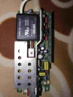
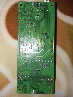
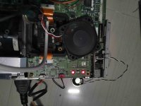
Photos of Ballast, Mother board and other related are attached.
Hello Everyone,
I'm trying to replace the OEM UHE 120W Lamp(ELPLP14) with 100W LED for my EPSON EMP 505 projector. I am facing the problem in bypassing the ballast. I have read a lot of posts and watched a lot of videos in which bypassing was done by shorting wires that go from mother board to ballast(This didn't work) and in others OSRAM bypassing was done (I haven't tried this one, as my projector doesn't seem to fit into these models).
All the information I have is:
1. 5 wires come out of the motherboard in which two are connected to FUSE Circuit of the Lamp and 3 go into Ballast Board.
2. Three wires that go to Ballast:
- Brown = 5V ( it gets applied thrice for 2 seconds having the time interval of 30 seconds. Then lamp error occurs, If there is no Lamp)
- Red = 0V looks like ground
- Orange = 2.71V (This seems to be the input to the motherboard from ballast)
3. I have taken out ballast and then shorted Brown & Red wires, then tapped the Orange wire to the Ground/Red when the 5V voltage showed up in Brown wire. This made the 5V supply in the Brown wire stay on for 20 seconds(which normally stays ON for 2 seconds). After 20 seconds, Power light and Temp light were blink in red color (According to manual it means "Circuit Malfunction").
At present I don't have the original lamp to check how it ideally works. It will be a great if anyone can help me solve this problem.
Photos of Ballast, Mother board and other related are attached.
Attachments
Remove ballast??? Best bulb suggestion.
Hello I am in the middle of my project here for an Infocus IN3134a. I grounded the wire and it all turns on fine. Now I have two questions:
1. I saw a video on youtube and a guy removed the ballast after bypassing it. Mine is hard to reach is it ok if i leave it there? Or should i remove?
2. Which currently are the best recommended bulbs?
I have my eyes on these but I prefer getting something that does not involve an LED driver.
LED COB Chip + Power Supply Driver 12V 100W 50W 30W 20W 10W For Flood Light Bulb | eBay
Which two lead should I short? Can I completely remove this ballast board and use LED instead? If so, How to fool the motherboard?
Thanks guys!
Thanks guys!
An externally hosted image should be here but it was not working when we last tested it.
Hi all,
I have a useful contribution to make, but bear in mind, safety is really important, so this should be undertaken by electrical and electronics engineers [disclaimer]
This follows on from work on the Russian forum at womebib622@ecofreon.com
Thanks for great work! I wanted to do this myself but I had no working bulb to discover the protocol and messages. So I found a cheap solution. I had a spare Metal Halide bulb used for garden lights, spot lamps, shops etc. It is the same technology as a UHP lamp, but cooler temperature and lower pressure.
I extended the lamp plug wires by soldering extra wire. I soldered the ends to the lamp. Make sure to use the same thickness and insulation of wire and insulate joints. I kept the lamp in a thick glass jar for more insulation and a blocker so I don't get eye damage. The voltage can be 20,000 Volts so make sure you don't get electrocuted. Only trained persons should do this.
The lamp worked perfectly and was even brighter than a UHP lamp. I think UHP is 12000 lumens for 200W, but my lamp is 20,000 lumens!! So this is a procedure just for capturing the protocol messages. I did not do this because I was happy with this lamp and can build my own projector with this ballast and LCDs. This spare lamp is £7 and the UHP lamp is £55. Also my lamp lifetime is 16,000 hours. So, hope this helps someone, and be safe <3body,div,table,thead,tbody,tfoot,tr,th,td,p { font-family:"Liberation Sans"; font-size:x-small }a.comment-indicator:hover + comment { background:#ffd; position:absolute; display:block; border:1px solid black; padding:0.5em; }a.comment-indicator { background:red; display:inline-block; border:1px solid black; width:0.5em; height:0.5em; }comment { display:none; }
body,div,table,thead,tbody,tfoot,tr,th,td,p { font-family:"Liberation Sans"; font-size:x-small }a.comment-indicator:hover + comment { background:#ffd; position:absolute; display:block; border:1px solid black; padding:0.5em; }a.comment-indicator { background:red; display:inline-block; border:1px solid black; width:0.5em; height:0.5em; }comment { display:none; }
To add to the above, I now have the pinout for the main power connector to the motherboard of my Epson EB-X11. Don't assume all models are the same.
It is labelled CN2000 on the PCB with the pins counting from left to right in descending order 10 to 1.
10) GND
9) 2.76 V
8) 7.15 V
7) 17.85 V
6) GND
5) GND
4) 5 V
3) 5 V
2) 3.14
1) 3.14
Measured twice, once on cold start, once on hot start.
The exhaust fan wires are:
Red 13.1 V
Black GND
Blue - either tacho or PWM
Brown - either tacho or PWM.
I will update when I know. This is for people who want to use LEDs and might need to change their cooling or other things. I have built LED projectors before, it is fun but incredibly time-consuming.
Also beware that some of these PSUs seem to not have bleeder resistors, so check everything is discharged with a meter before delving in. Sorry about the formatting at the end of my last post.
OK, checked with an oscilloscope.
Exhaust fan wires:
Blue - Tachometer 8kHz signal when cold from Hall sensor. 4 poles NSNS implies 4000 RPM.
Brown - PWM 50% duty cycle 5V square wave at cold start. 99% at full load. Pulls low to switch off the fan.
Exhaust fan wires:
Blue - Tachometer 8kHz signal when cold from Hall sensor. 4 poles NSNS implies 4000 RPM.
Brown - PWM 50% duty cycle 5V square wave at cold start. 99% at full load. Pulls low to switch off the fan.
Looking for a mosfet used in JVC 4910 ballast. It is a 19n60e ( Fe , Fuji electric )
Maybe one pulled from an old ballast even
Maybe one pulled from an old ballast even
I wish it was this easy for me. I have a sanyo projector and this is what I see
No lamp
1-constantly changes between 1-3-5
2-0v
3-1 then 5 when on
4- constant 5v
5- constant 5v
With lamp
1-1 and 4 In boot before back to 1
2-0v
3-1 then 5 when on
4- 5v then 3 when on
5- constantly 5v
No lamp
1-constantly changes between 1-3-5
2-0v
3-1 then 5 when on
4- constant 5v
5- constant 5v
With lamp
1-1 and 4 In boot before back to 1
2-0v
3-1 then 5 when on
4- 5v then 3 when on
5- constantly 5v
Hi guys
I thought I'd come here and update the thread with another successfull ballast bypass on a BenQ MS500+.
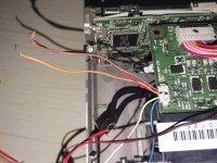
On the mainboard look for the 5 set of wires coming from ballas to the board. Its J13 port:
Disconnect Yellow wire on the mainboard (PIN 5-TP48) -1st wire from left, and earth it to the body. Youre done!
Attached pic below is to show the connector J13 and wire set - ignore those disconnected wires (I cut them off for other purposes)

I thought I'd come here and update the thread with another successfull ballast bypass on a BenQ MS500+.
On the mainboard look for the 5 set of wires coming from ballas to the board. Its J13 port:
Disconnect Yellow wire on the mainboard (PIN 5-TP48) -1st wire from left, and earth it to the body. Youre done!
Attached pic below is to show the connector J13 and wire set - ignore those disconnected wires (I cut them off for other purposes)
Hello good sir, did you ever managed to bypass Sanyo PLV Z2 ? i have one with still working bulb, but want to put inside led to use it all day long...Hello, I am new here and I am trying to bypass the lamp on a Sanyo PLV Z2. The projector lamp ballast comes out with only two contacts/wires so I don't know how it detects the bulb. I am planning to convert this to LED using a Cree XML.
Sanyo PLV-Z2
After further research I realized that I assumed the "ballast" was the housing the lamp was held in, but I may be wrong. I found the projector schematics and the details of the connection to the ballast is shown in the attached image. It appears there are 5 wires connecting the ballast to the board.
1. LAMP_SENS.
2. GND
3. 5V
4. LAMP_SW
5. ECO
I assume that 1 is most likely the lamp sensor, do you think this will have the 3.5v that needs to be grounded?
Ok i opened i removed power supply cables to ballast (3 wire), then i disconnected from ballast this 5 wires (that goes to main board)...
After turning on projector and measure... PIN 1. and PIN 5(ECO) have always 5+ volts... PIN 4. sometimes 0.4 sometimes 1v but PIN 3. have 5v in begging when projector starts then when projector goes red light blinking it goes to almost zero voltage... so should jumping and giving 5v on PIN 3 trick projector that everything is ok? or should be grounded maybe? Please help someone 🙂
- Home
- General Interest
- Everything Else
- The Moving Image
- DIY Projectors
- Commercial Projector Ballast Bypass Guide