My next problem is the measurement of the DC Output Voltage - I measure -9.61V at both speaker terminals, regardless of the position of the volume pot. Any ideas as to why?
This is completely unacceptable and wrong, check if the resistor values are correct in each location.
Also, the angle to which chips are attached looks paper thin, what the bottom of the chassis is made of (aluminum or steel) and what thickness?
If you can't find the problem post detailed pictures of the whole circuit.
Start from the start. The first problem was the humming transformer. Is there a rectifier? I dont see it but guess its on the chassis wall. No psu board? Why are you building this "seat of your pants".."whatever I've got lying around"? Peter supplies build guides. No heatsink? For real? Jeeze. 0V only developed once DC from hidden rectifier hits the amp board? Even if you get it working PSRR will not be good and you will probably be plagued with grounding problems. I think you need to take it apart and start over while adding a psu board and sink.
The psu board is right beside transformer on a chassis wall. I don't see any major problems with the build itself, just the angle where chips are mounted should be thicker (and the bottom preferably aluminum).
The excessive offset is most likely due to some unfortunate mistake.
The excessive offset is most likely due to some unfortunate mistake.
Hi Peter,
Thanks for your measured reply. The chips are mounted to a thin aluminium angle however it is bolted to 3mm aluminium plate - the whole chassis is aluminium. I shall flip the angle over and mount the chips directly to the 3mm aluminium chassis floor. Will this suffice?
Sorting through the unnecessary rhetoric of other comments, I will disassemble the amp in order to trace the fault. The weekend is here so hopefully I'll be able to resolve the issue and report a positive result by Sunday!
Cheers,
Tim
Repainting powdercoated alu - a problem?
Hi again,
Thank you for your quick replay.
I'm in the process of spray-painting the outside of my chassis into a grey brownish colour that I got from an vintage Quad 33 pre amp.
My concern:
1. Is it OK to repaint with compressor and airbrush on already powder coated metal? Remember these Parts will only be painted on the outside of the chassis.
I have sanded all surfaces before repainting.
2. All parts in my chassis are 1mm thick. Will these chassis work well enough as heat sinks- or should I get a hold of an heat sink for the main chassis with the lm3875 boards inside?
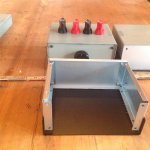
PS: see attached picture - still in progress.
Thank you!
Hi again,
Thank you for your quick replay.
I'm in the process of spray-painting the outside of my chassis into a grey brownish colour that I got from an vintage Quad 33 pre amp.
My concern:
1. Is it OK to repaint with compressor and airbrush on already powder coated metal? Remember these Parts will only be painted on the outside of the chassis.
I have sanded all surfaces before repainting.
2. All parts in my chassis are 1mm thick. Will these chassis work well enough as heat sinks- or should I get a hold of an heat sink for the main chassis with the lm3875 boards inside?
PS: see attached picture - still in progress.
Thank you!
Attachments

1mm thick aluminium works very well at transferring heat upto ten times it's thickness, i.e. to 10mm away from the chip contact interface.
Beyond ten times thickness, aluminium becomes less effective.
By the time you are out at thirty times, you will find that the aluminium panels are getting noticeably cooler than directly under the chip. This equates to low dissipation capability.
A 3mm thick panel will be much more effective, if you really want to try avoiding the use of a proper heatsink, roughly twice the National guidelines given in the datasheet.
Heatsink
Hello again,
* I want to use the chassis I already got ; which all panels has a thickness of 1mm.
** can anyone direct me to a proper heatsink for the LM3875 chip?
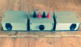
*** the chassis I'm currently using are 80mm high, 180mm in width and 150mm in depth.
**** adding a picture of the inside compartment same as all three chassis used for this build.
***** crossing fingers that the suitable heatsink will fit into this chassis.
PS: I will only need to implement heatsinks on the two LM3875 chips in the main chassis - Correct?
Hello again,
* I want to use the chassis I already got ; which all panels has a thickness of 1mm.
** can anyone direct me to a proper heatsink for the LM3875 chip?
*** the chassis I'm currently using are 80mm high, 180mm in width and 150mm in depth.
**** adding a picture of the inside compartment same as all three chassis used for this build.
***** crossing fingers that the suitable heatsink will fit into this chassis.
PS: I will only need to implement heatsinks on the two LM3875 chips in the main chassis - Correct?
Attachments
Attachments
LM3875 chip does need much heat sinking, just check my Patek chassis, which is much smaller than your enclosure and the sides are made of wood.
The produced heat will depend on speakers load and how loud you play the music. In some cases your chassis even without modifications would be fine, however, I wouldn't count on that.
I think your best bet would be adding thicker aluminum panels to the sides (6mm or so). That will help with heat transfer to the rest of the enclosure, chips would be on each side, mounted to reinforced panels, if that's not enough you can always attached proper heatsinks on the outside later.
Sorting through the unnecessary rhetoric of other comments, I will disassemble the amp in order to trace the fault. The weekend is here so hopefully I'll be able to resolve the issue and report a positive result by Sunday!
Check your soldering and grounding. With offset like that, it could be resistor misplaced or missing.
R1 220R
R2 22k
R3 680R
Rfb 22k
When the amp works properly, moving the potentiometer should affect offset reading in [0-60mV] range
Hello Tralalalala,
What about some aluminum profile from this webshop: Hoekprofiel ongelijkzijdig 6060T66 bestellen
It is inexpensive and they cut to length for you in nice rectangular way.
Take for example 30x50x5mm. You could connect/bolt them to the steel sides from the inside with some heat transfer compound.
For example take two lengths of 100mm: Hoekprofiel ongelijkzijdig 6060T66 bestellen
One for each chip?
Alternatively you could attach the narrow part to the bottom and leave some air between the aluminum and the steel plate at the side but I guess in that case you would need to have venting slots in your top and bottom plates to get rid of the hot air.
Regards, Frederick Joan
have a look at their website, there are many profiles and dimensions; T, L, U-shaped etcetera.
I am sure there will always be something you need....
Frederick
I am sure there will always be something you need....
Frederick
Check your soldering and grounding. With offset like that, it could be resistor misplaced or missing.
R1 220R
R2 22k
R3 680R
Rfb 22k
When the amp works properly, moving the potentiometer should affect offset reading in [0-60mV] range
Hi Peter,
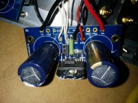
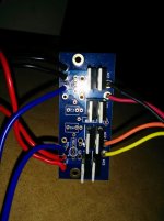
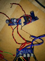
I don't have R1 installed instead I am using a jumper wire. I have included a photo of the amp board. Is it correct?
Attachments
The output ground from the back of the speaker ground connection is connected to another wire which is then to 16 GA copper wire. From the rectifier board there are two wires connecting to the 16 GA copper wire. The 16 GA copper wire was connected to the chassis ground. It's not exactly like what you have shown but I think it's close???
Does it matter which combination of V+ & V- pads are used to connect from the rectifier to the amp?
Does it matter which combination of V+ & V- pads are used to connect from the rectifier to the amp?
Attachments
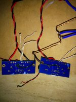
Doesn't matter which pads.
And the wiring seems to be fine.
So, I don't really know what could make for such a high offset
And the wiring seems to be fine.
So, I don't really know what could make for such a high offset
Would it have anything to do with the potentiometer?
The offset is several orders of magnitude higher than it should be. Does that indicate a short circuit either from a bad solder joint or defective chip? In the case of a bad solder joint I can strip the board down and re-solder. How would I test for a faulty chip or other faulty parts for that matter?
I'm going to call it a night for now...fresh eyes in the morning may help!
Thanks for your assistance Peter!
Good Night!
Shouldn't have anything to do with a pot as it doesn't matter if the input is grounded or left floating or shunted through any resistance: the output should show a reasonable offset value (less than 100mV) in any case.
There's also no reason to strip anything from the board: just apply some liquid rosin flux to all joints and reheat them again with solder gun, it's the best way to make sure the soldering is fine. It will fix any cold joints or bridges: No Clean Liquid Rosin Flux - 4 oz.
I would suggest testing a single amp board first by connecting it directly to rectifier board as pictured here: http://www.diyaudio.com/forums/audi...ne-kit-building-instructions.html#post1508961
If your soldering is fine, resistors not mixed up and still offset, I can only suspect that chip might be damaged.
Easiest way to check if the chip works is to shunt the input: the offset should go down. If nothing happens, the chip is most likely damaged.
- Home
- More Vendors...
- Audio Sector
- Commercial Gainclone kit- building instructions