thank you for the fast answer Andrew,
It is clear to me that i have to connect both chassis to the PE in some way, but I am a little bit confused which way is the best to do that. Would a 5ths cable in the umbilical to connect the amp chassis with PE the best solution?
It is NOT clear to me, why it is necessary to connect the star point of star power ground to the PE...
maybe you can help me with that.. ?
Regards, Henrik
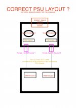
I would like to add a sketch to my question, maybe that makes things easier. (Sorry for the childisch look, my painting skills aren't that good)
Is this correctly wired?
Do i need a connection between PE (chassis) and the star point?
I've read in this thread that it is possible to connect PG+ and PG- next to the rectifier board, for using a three wire umbilical (that makes sense to me). Is it possible to use that wire for PE, too?
you see, there is a lot of confusion for me I hope you can help me with that 🙂🙂
Attachments
There is a long Thread from 5 or more years ago discussing this in detail. Many of the Safety issues were well explored.thank you for the fast answer Andrew,
It is clear to me that i have to connect both chassis to the PE in some way, but I am a little bit confused which way is the best to do that. Would a 5ths cable in the umbilical to connect the amp chassis with PE the best solution?
It is NOT clear to me, why it is necessary to connect the star point of star power ground to the PE...
maybe you can help me with that.. ?
Regards, Henrik
I would like to add a sketch to my question, maybe that makes things easier. (Sorry for the childisch look, my painting skills aren't that good)
Is this correctly wired?
Do i need a connection between PE (chassis) and the star point?
I've read in this thread that it is possible to connect PG+ and PG- next to the rectifier board, for using a three wire umbilical (that makes sense to me). Is it possible to use that wire for PE, too?
you see, there is a lot of confusion for me I hope you can help me with that 🙂🙂
Your sketch looks fine. I prefer to run PG+ and PG- separately and connect them together in the amp.
It's also my experience that when output ground is not connected with the amp chassis (even when that one is connected to PE) all sort of noise may occur.
Thankyou for your Answer Peter,
In the meantime I followed Andrews advice and learned some things about grounding of audio components. I found this on the Forum, maybe it will help other beginners too! http://www.diyaudio.com/forums/diyaudio-com-articles/163575-audio-component-grounding-interconnection.html
especially the "design rules" and the short chapter about grounding a PSU is helpful.
there is just a little bit of confusion left. In the pictures of the Patek amp v2 there is no seperate wire for mains ground in the umbilical. I've learned that there should be a direct connection between mains ground and chassis. I don't understand how this is realized in this specific case.
there is just a little bit of confusion left. In the pictures of the Patek amp v2 there is no seperate wire for mains ground in the umbilical. I've learned that there should be a direct connection between mains ground and chassis. I don't understand how this is realized in this specific case.
I simply didn't runt that wire in the umbilical, if there is a need for such wire, you can connect the two chassis externally.
GC kit questions
I have some questions. I'm a novice amp builder, though I've made speaker crossovers and cables successfully. I lucked into one of the Special K GC kits, with some upgraded parts, and have been looking at both the LM3875 building guide Peter has on his site, and some updated preferences he developed after making the guide. I'd like to doublecheck I have the parts ID'd correctly and am using the most "recent" build ideas.
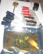
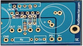
First, resistor questions. The original instructions show R1, R2, R3, and Rf on the board.

On the Audiosector site the board has no R1 resistor, and the Rf resistor is mounted right on the LM3875. (I saw directions on this site for doing that.)

Question 1: The directions mention the R1 is optional and Peter says he often just uses a wire; but there is no wire in the later photo, so I guess the current practice is to put nothing there? The parts I have would suggest that, because I have the square 22K resistors and a pair of big R3 680R resistors, but no R1 pair.

Question 2: The single little resistor is I assume the one needed on the rectifier board if I mount the LED. There are images with and without and I believe it is optional to use it?


I have some questions. I'm a novice amp builder, though I've made speaker crossovers and cables successfully. I lucked into one of the Special K GC kits, with some upgraded parts, and have been looking at both the LM3875 building guide Peter has on his site, and some updated preferences he developed after making the guide. I'd like to doublecheck I have the parts ID'd correctly and am using the most "recent" build ideas.
First, resistor questions. The original instructions show R1, R2, R3, and Rf on the board.
On the Audiosector site the board has no R1 resistor, and the Rf resistor is mounted right on the LM3875. (I saw directions on this site for doing that.)
Question 1: The directions mention the R1 is optional and Peter says he often just uses a wire; but there is no wire in the later photo, so I guess the current practice is to put nothing there? The parts I have would suggest that, because I have the square 22K resistors and a pair of big R3 680R resistors, but no R1 pair.
Question 2: The single little resistor is I assume the one needed on the rectifier board if I mount the LED. There are images with and without and I believe it is optional to use it?
Attachments


Last edited:
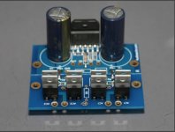
Also, some cap questions. I have four little Panasonic caps, and twice as many diodes as I need, I assume because the original kit was for two monoblock amps, with two transformers.
Question 3: The two little red BG caps are for the kit that was developed to go into the "Specialized" chassis, with one transformer and one rectifier board, correct?
Then I have four Panasonic 1500 uF caps; four BG 100 uF caps; and two BG 1000 uF caps.

The four caps are either/or possibilities for the amp boards, I believe. On the "Audiosector chip amp" thread Peter says, in post 251, "I presently favour 100/50 BG N caps directly beside the chip and 1000/50 BG STD on rectifiers board."
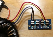
Question 4: Where do the big BG caps go on the rectifier board? The same spot where the little red BG caps would otherwise go? The only picture I could find with the BG 1000 uFs was a review shot, and there the BG caps looked to be mounted on wires to the board presumably because of space restrictions inside the chassis.

Question 5: Peter somewhere he says he likes the BG cap pairing (on the amp and rectifier boards) for the full-range speakers he prefers to listen to. As I prefer generally to listen to speakers with a woofer and tweeter, and a crossover in them, am I better off installing the four Panasonic caps on the amp board?
Question 6: The boards are scored and meant to be separated. Can I just bend them at the score and expect them to break cleanly? or do I need to cut them with a dremel or something?
Sorry to ask so many questions. I'm thrilled to have the amp and don't want to eff it up.
Question 3: The two little red BG caps are for the kit that was developed to go into the "Specialized" chassis, with one transformer and one rectifier board, correct?
Then I have four Panasonic 1500 uF caps; four BG 100 uF caps; and two BG 1000 uF caps.
The four caps are either/or possibilities for the amp boards, I believe. On the "Audiosector chip amp" thread Peter says, in post 251, "I presently favour 100/50 BG N caps directly beside the chip and 1000/50 BG STD on rectifiers board."
Question 4: Where do the big BG caps go on the rectifier board? The same spot where the little red BG caps would otherwise go? The only picture I could find with the BG 1000 uFs was a review shot, and there the BG caps looked to be mounted on wires to the board presumably because of space restrictions inside the chassis.
Question 5: Peter somewhere he says he likes the BG cap pairing (on the amp and rectifier boards) for the full-range speakers he prefers to listen to. As I prefer generally to listen to speakers with a woofer and tweeter, and a crossover in them, am I better off installing the four Panasonic caps on the amp board?
Question 6: The boards are scored and meant to be separated. Can I just bend them at the score and expect them to break cleanly? or do I need to cut them with a dremel or something?
Sorry to ask so many questions. I'm thrilled to have the amp and don't want to eff it up.
Attachments

Last edited:
Q1: no resistor as I attach the input wire directly to one of the pads.
Q2: that resistor is indeed for the LED and it's optional
Q3: I don't see any 2 small BG caps in your pics. If you have them and those are 10/50, then they would normally go on rectifier board. And this is still my favorite arrangement: 100/50 BG N caps directly beside the chip and 1000/50 BG STD on rectifiers board
Q4: The big BG STD caps go indeed on rectifier board, no need for small BG N there then.
Q5: If there is a choice between 6 BGs and 4 Panasonic caps, I would definitely go with BGs. Note that those BGs are worth at least $50 ea. now, so you might sell them and go with Panasonics which are still quite good.
Q6: If you bend the boards they will separate easily.
Attachments

Hi Peter,
I am waiting on the arrival of my LM3875 Premium kit (hope it comes soon!!!) and was wondering where to get a Noble Pot from (as suggested in the first couple of pages of this thread) Percy's only have 250K Ohm available - is this suitable and will it be vastly different from the 50 K item? Could you offer an alternative item also? I'm keen to follow your advise closely as this will be my first DIY Amp and have sunk more money into than anticipated so don't want to vary from the original design. Thanks in advance.
Tim
get a temporary vol pot.
You could try a 10k plastic film type and try a 20k carbon track type and a 50k cermet type.
Listen to what you hear. Do any sound any different? Try to identify why the difference is apparent.
Then when you have found your Noble retailer you can order the correct value.
You could try a 10k plastic film type and try a 20k carbon track type and a 50k cermet type.
Listen to what you hear. Do any sound any different? Try to identify why the difference is apparent.
Then when you have found your Noble retailer you can order the correct value.
Several Questions About the Build...
Hi !
I`ve just ordered a LM3875 kit.
(with additional rectifier diodes for a dual mono amplifer )
I do have some questions regarding the build:
1. I will need 230VAC Power Entry Module. - This exact item was recommended for me for another build that I never completed. The AC Entry Module is from Schaffner:
FN284-2-06 Schaffner | Mouser
Is this a good choice?
I´ve tried to read the manaul for the LM3875 build thoroughly on the Audio Sector Webpage - the same as in this thread….
2. The 230VAC Power Entry Module ( see link above ) has a 2 A ( will install slow burn ) fuse. Will this be enough? - or should I use a Power Entry Module with a 2.5A ( will install slow burn ) fuse ?
3. I´m planning on using two ModuShop Galaxy Chassis ( modu ) that I already have (230mm x 230mm ) for this build; one for the dual power supply and one for the LM3875 chip amp.
Is it correct to install female XLR connectors in the chassis for the amp and male XLR connectors in the power supply chassis?
4. Any suggestions on what type of power cable I should use for the two XLR cables that will be between the power supply and the amplifier?
5. I see that there are a lot of electrical measurement tools that I do not have described in the last pages of the manual on Audosectors webpage.
Will a Multimeter be sufficient to do the last required measurements described in the manual?
6. Is there a possibility to install diodes in the chassis of the chip amp?
7. I have a DACT CT2-10K stepped attenuator ( DACT audio attenuators ) already installed in a separate chassis ( unit ) - will this stepped attenuator work well as a volume control for this chip amp? Should I install it directly in the chip amp module or can I just use it in the separate chassis where it is already installed?
All help will be appreciated !
Thanks !
2A allows for 460VA (virtually continuously). Do you need that much?
1A does most domestic duties.
The higher the current rating the lower the filtering performance. Size determines what can be fitted inside.
Buy a cheap DMM that has a 199.9mVac scale as well as the more usual AC and DC scales.
As you gain experience you may decide to buy/build more sophisticated instruments.
A remote vol pot is very useful.
It can be placed where the operator can get to it easily.
The Power Amplifiers tend to be next to the speakers. That is generally the wrong place for a vol pot.
BUT !!!!!
a remote vol pot requires a Buffer to drive the cable interconnects running the the next stage in your system.
That is why we see so many Buffer projects. B1, DCB1, Juma, Calvin, Peranders, ...... etc.
The B1 and the DCB1 have provision for the vol pot on the PCB.
Last edited:
Hi !
I`ve just ordered a LM3875 kit.
(with additional rectifier diodes for a dual mono amplifer )
I do have some questions regarding the build:
1. I will need 230VAC Power Entry Module. - This exact item was recommended for me for another build that I never completed. The AC Entry Module is from Schaffner:
FN284-2-06 Schaffner | Mouser
Is this a good choice?
I´ve tried to read the manaul for the LM3875 build thoroughly on the Audio Sector Webpage - the same as in this thread….
2. The 230VAC Power Entry Module ( see link above ) has a 2 A ( will install slow burn ) fuse. Will this be enough? - or should I use a Power Entry Module with a 2.5A ( will install slow burn ) fuse ?
3. I´m planning on using two ModuShop Galaxy Chassis ( modu ) that I already have (230mm x 230mm ) for this build; one for the dual power supply and one for the LM3875 chip amp.
Is it correct to install female XLR connectors in the chassis for the amp and male XLR connectors in the power supply chassis?
4. Any suggestions on what type of power cable I should use for the two XLR cables that will be between the power supply and the amplifier?
5. I see that there are a lot of electrical measurement tools that I do not have described in the last pages of the manual on Audosectors webpage.
Will a Multimeter be sufficient to do the last required measurements described in the manual?
6. Is there a possibility to install diodes in the chassis of the chip amp?
7. I have a DACT CT2-10K stepped attenuator ( DACT audio attenuators ) already installed in a separate chassis ( unit ) - will this stepped attenuator work well as a volume control for this chip amp? Should I install it directly in the chip amp module or can I just use it in the separate chassis where it is already installed?
I don't like using filtered power entry modules, the amp sounds better without any AC filtering, so this is what I use: 761-18/003 Qualtek | Q300-ND | DigiKey
If you want XLR connector for PS umbilical, use 4 pin version with female socket on PS enclosure.
Multimeter is fine enough for testing the amp, the other equipment shown there was only to present the power outputs.
Sure, you can install diodes in the amp, although I prefer to run DC voltages in the umbilical.
10k attenuator is a good choice for the amp, and it's always best to install attenuator directly at amp's input. When putting attenuator in a separate chassis, another set of interconnects needs to be used and the passive circuit is not always "comfortable" with this addition.
Hi Peter,
I am waiting on the arrival of my LM3875 Premium kit (hope it comes soon!!!) and was wondering where to get a Noble Pot from (as suggested in the first couple of pages of this thread) Percy's only have 250K Ohm available - is this suitable and will it be vastly different from the 50 K item? Could you offer an alternative item also? I'm keen to follow your advise closely as this will be my first DIY Amp and have sunk more money into than anticipated so don't want to vary from the original design. Thanks in advance.
Tim
Noble pots have been discontinued and what what Percy sells is the remaining stock only. 250k is way too much for a chip amp.
Use blue Alps available from partsconnexion; I'd go with 10k value, while 50k would be the maximum.
Hi !
Thanks for both of your replies!
Good. I have a Digital Multimeter that can read mV AC.
Andrew: Thanks about the input on using a buffer when using a remote volume pot. I have seen the Buffer Project by Nelson Pass on net - didn't know there were that many DIY projects out there too …. ;-)
I guess I will install my 10K DACT volume controller inside the LM3875 amplifier then, but maybe a project for the future will be a Buffer Project.
Peter: Good to know about your opinion about filtered Mains Entry Modules- will choose an unfiltered Mains Entry Module for this project then.
Regarding the XLR connectors, I will use 4-pin female XLR connectors on the Power Supply Module - and then do as you do on your finished builds of the PATEC v2 with just running the power chord through the chassis of the LM3875 amplifier chassis.
Thanks!
Endre
Where to place the PSU boards...
Hi again,
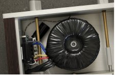
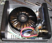
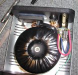
I need someone to confirm my assumptions regarding placement of the PSU boards.
I will use as Peter recommended by email; two Torodiy Audio Transformers with 230V primary and 2x25V secondaries for my 16 ohm speakers.
See attached JPEG files.
I will need to place the PSU boards inside the same chassis of the Torodiy Transformers - right?
I will need two XLR cables between the PSU chassis and Amplifier chassis ( one cable for each channel ) - right ?
Endre
Hi again,
I need someone to confirm my assumptions regarding placement of the PSU boards.
I will use as Peter recommended by email; two Torodiy Audio Transformers with 230V primary and 2x25V secondaries for my 16 ohm speakers.
See attached JPEG files.
I will need to place the PSU boards inside the same chassis of the Torodiy Transformers - right?
I will need two XLR cables between the PSU chassis and Amplifier chassis ( one cable for each channel ) - right ?
Endre
Attachments
Good.
This time I did try to search this thread... ;-)
I´m trying to figure out what type of power cable that is suited for between the power chassis and the amplifier chassis.
What type of cable do you recommend?
What type of internal wires should I use between :
between the PSU board and the XLR female chassis connectors?
- Home
- More Vendors...
- Audio Sector
- Commercial Gainclone kit- building instructions