Thank you,
I just now got a comment that I better use metal screws to mount the chips.
will that not short the chip to the heat-sink?
I just now got a comment that I better use metal screws to mount the chips.
will that not short the chip to the heat-sink?
You can only use metal screws if you have insulators. Why did you not use paste, it helps with the cooling by sealing any small gaps in the metal?
Unless they are the plastic coated ones with no metal showing on the back, then you can use metal screws.
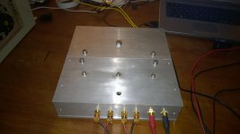
They look like TF package chipamps.
They already have the electrical insulation.
One does not need to add in extra Thermal Resistance by using Thermal Pads.
Just smear a thin layer of Thermal Goop on the back of the TF and then bolt it down very gently. Rotate the chip in the slack around the bolt slots to spread the Goop around and push the trapped air out to the perimeter. Tighten slightly to increase the pressure on the GOOP+AIR and keep rotating until no more Goop exudes from the edges. Now tighten down firmly.
While doing the "rotating" you MUST take care to not strain the leadouts. This is easier if you solder AFTER the final bolting down.
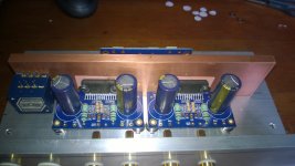
This type of the LM4780 has no own insulation so it needs insulation pads.
I used silica pads, it needs no extra paste for heat conduction
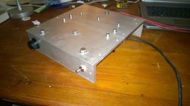
Here the changes I made after some helpful comments,
I changed the nylon screws with metal ones and put stands to hold the PCB in place
I used silica pads, it needs no extra paste for heat conduction
Here the changes I made after some helpful comments,
I changed the nylon screws with metal ones and put stands to hold the PCB in place
Attachments
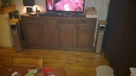
The amp is working!!!!
It sounds great, zero hum or other noises, first time run and perfect
Now finishing the casing.
Thanks Peter for this great design.
After playing loud for some time it all becomes quiet warm, maybe have to add an extra heat-sink on the top?
Anyway, here a very happy guy.
Greetz
It sounds great, zero hum or other noises, first time run and perfect
Now finishing the casing.
Thanks Peter for this great design.
After playing loud for some time it all becomes quiet warm, maybe have to add an extra heat-sink on the top?
Anyway, here a very happy guy.
Greetz
Attachments

Last edited:
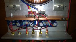
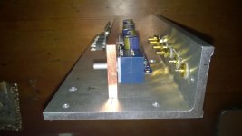
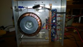
I would worry a little about the cables touching the copper bar. The chances are they will melt. Correct me if i am wrong.
Nick
Nick
They are already touching the copper bar. He has a bolted connection way off towards the right hand end.I would worry a little about the cables touching the copper bar. The chances are they will melt. Correct me if i am wrong.
Nick
It's these wires that prevent thermal coupling of both the lid and the floor. He can only do one not both.
Prevent thermal coupling with the floor? No i think the floor is coupled (or should be ) with the copper bar and the cable should pass either from the side which has a gap, or from a hole that should be opened in the copper.
As far as the top goes i agree with you.
Nick
As far as the top goes i agree with you.
Nick
The copper bar is bolted to the aluminum chassis, I don't think the heat-sink will reach temperatures that will melt the insulation of the cables.
What worries me tho is that the amp will get quiet warm even when not playing. Because the fuse in my multimeter is blown I can not measure the current.
Is there a "rest current" in the LM4780 like a class A amp.?
Regards,
Joery
What worries me tho is that the amp will get quiet warm even when not playing. Because the fuse in my multimeter is blown I can not measure the current.
Is there a "rest current" in the LM4780 like a class A amp.?
Regards,
Joery
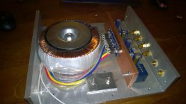
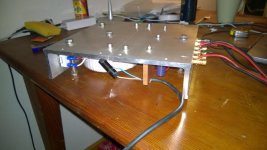
If it was maybe not clear but the design is that the bottom of the amp will float. The thickness of the toroid is bigger then the hight of the chassis so I will make stands on the chassis (one hole already made) to make the amp float and the chassis and copper bar will never touch the floor.
Attachments
That tells me there is something wrong with the DC blocking input capacitor.Btw, the DC voltage at output is 45 mV with volume at max and 4 mV with volume off
It could be leaking badly or fitted in the wrong location, or omitted.
Are your voltages DC?
i.e. 45mVdc and 4mVdc?
If you can connect the copper bar to more of the thick aluminium case, the chip/s will run cooler.
What about the previous suggestion to run the 5 enameled wires THROUGH the copper bar and then Thermally connect the bar to the bolted down lid?
What about the previous suggestion to run the 5 enameled wires THROUGH the copper bar and then Thermally connect the bar to the bolted down lid?
That tells me there is something wrong with the DC blocking input capacitor.
It could be leaking badly or fitted in the wrong location, or omitted.
Are your voltages DC?
i.e. 45mVdc and 4mVdc?
The voltages are DC and what read in the previous comments the values are within limits.
I don't use input caps as they can make the sound quality worse.
I will leave the bottom of the amp open so if I need more heat dissipation i have to put a heat-sink on top of the amp.
This time I'm listening to the amp and must say it REALLY sounds great.
Peter together with the inventors of the LM4780 are great.
Thanks for that.
Greetz,
joery
Weird enough I found out that the temp of the amp with no load is getting less after playing it for longer time?!
The neighbors are on holiday now so I pushed the amp to max for quiet some time and it performs well, its getting quiet warm but without any problems.
The combination of this amp with my speakers (Mission M52) is perfect.
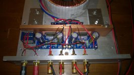
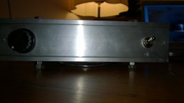
On the pics you can see the stands its resting on, the power connection is not good yet, in the future I will make it nice.
Now I'm using a 6A slow fuse.
The coming days I will make the side panels from oak wood and I will replace the volume knob with a nice aluminum one.
All the bolts are from stainless steel.
Greetz,
Joery
The neighbors are on holiday now so I pushed the amp to max for quiet some time and it performs well, its getting quiet warm but without any problems.
The combination of this amp with my speakers (Mission M52) is perfect.
On the pics you can see the stands its resting on, the power connection is not good yet, in the future I will make it nice.
Now I'm using a 6A slow fuse.
The coming days I will make the side panels from oak wood and I will replace the volume knob with a nice aluminum one.
All the bolts are from stainless steel.
Greetz,
Joery
Attachments


Now I'm using the output from my laptop and its actually not bad, In the future I will get a DAC to improve the sound quality.
I'm thinking about the dragonfly 1,2, it seems to preform good. Any comments about that?
Greetz,
Joery
I'm thinking about the dragonfly 1,2, it seems to preform good. Any comments about that?
Greetz,
Joery
Now I'm using the output from my laptop and its actually not bad, In the future I will get a DAC to improve the sound quality.
I'm thinking about the dragonfly 1,2, it seems to preform good. Any comments about that?
Greetz,
Joery
I do not see the power supply caps!😱
Am I blind?😕
- Home
- More Vendors...
- Audio Sector
- Commercial Gainclone kit- building instructions