the 4780 in parallel mode (BPA100) into 4ohms will operate on +-30Vdc. You can go up to +-34Vdc but you will need a very big heatsink, because the 4780 has a poor thermal resistance (Rth c-s).alkasar said:building the LM4780 dual mono kit (parallel mode). I have 4ohms loudspeakers.
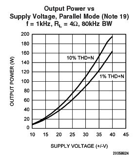
................graph below is from the LM4780 datasheet. This suggests that 30V DC or even more is adequate. Is this correct ?
Even at +-30Vdc the sink will be quite big.
kele1975 : correct, diagram on page 1 is for LM3875. i did not find recomandations for LM4780 kit supply voltage.
Andrew : would you consider that a heatsink 100x200x43mm with 0,7°C/W is sufficient ? (one heatsink for both chips)
Andrew : would you consider that a heatsink 100x200x43mm with 0,7°C/W is sufficient ? (one heatsink for both chips)
An externally hosted image should be here but it was not working when we last tested it.
4780 datasheet does not show recommended heatsinks for speaker and PSU combinations.alkasar said:would you consider that a heatsink 100x200x43mm with 0,7°C/W is sufficient ? (one heatsink for both chips)
I'll use the 3886 datasheet since the 4780 is two 3886 combined into one package.
P14 shows the National recommendations for heatsinking.
Using +-30Vdc and 8r0 (a single feeding 8r0 is similar to a BPA feeding 4r0), the graph predicts about about 22.5W of Pd.
Look across to the table and find Ta=25degC
We are between 3.8 and 5.1 for Rth s-a. Estimate Rth s-a~=4.5C/W
A two channel chip will require double this, i.e. ~2.2C/W
Two off two channel chips will require double again, i.e. 1.1C/W
Look at the conditions that National have chosen for their testing/guaranteed performance. You must de-rate the heatsink for low temperature operation. You must add on the resistance of the isolator interface. You should run the amplifier cooler than the maximum that National use for resistance loading when driving a reactive load, this to help avoid "Spike" triggering on current peaks when the chip internals are above 25degC. You must allow for the two channel chip having a higher thermal resistance than the 3886.
To take account of these I suggest you double the heatsink size again.
To run four channels (two 4780 chips) into 8ohms from +-30Vdc I would recommend 0.55C/W for cool running in ambient temperatures of <=25degC.
you confirm you understand, more importantly, is there anything you disagree with?alkasar said:Thanks andrew. Very clear. I undersand you reasoning and assumptions.
I would suggest that 4 * 3886 chips spread across the width of your 0.7C/W sink will probably perform adequately in comparison to 2 * 4780 chips on a 0.55C/W sink.
Potentiometer choice
Hi there, first post. I have an LM4780 stereo kit on the way [one amp board and one rectifier board] and from what I have gathered Peter likes to recommend a 25K pot for a nice volume response.
My supplier only has 10K or 50K pots. Which one would be more suitable for this kit?
Do I still use the 22K resistors for either of these pots or would I have to change resistors to suit either potentiometer?
I'll be using the pot until I choose a better solution later.
TIA...40 watt...I know, not too bright! 🙄
Re: Potentiometer choice
If you have an able source that can drive 10k//Ccable then select that for your pot.
depends on the ability of your source to drive the pot resistance and the interconnect cable.40 watt said:recommend a 25K pot
My supplier only has 10K or 50K pots. Which one would be more suitable for this kit?
If you have an able source that can drive 10k//Ccable then select that for your pot.
Re: Re: Potentiometer choice
Thanks Andrew. The chip amp is mainly for my computer which I assembled over the winter. Asus motherboard with, quoting the manual for the motherboard: "Enjoy high quality sound system on your PC! The onboard 8-channel HD audio [High Definition Audio, previously codenamed Azalia] CODEC enables high quality 192KHz/24-bit audio output, jack detect feature, which automatically detects and identifies what types of peripherals are plugged into the audio I/O jacks and notifies users of inappropriate connection, meaning there will be no more confusion of Line-in, Line-out and Mic jacks."
I previously had an old Onkyo Integra integrated amp plugged into the lime green jack with an RCA adaptor but of course the Onkyo had a preamp section, and the chip amp doesn't. I had envisioned plugging the chip amp into the same lime green jack for two channel.
Is there anything I should be aware of to make the chip amp work well with the computer, perhaps especially so regarding volume pot?
I'm not really tech savvy, as you could probably tell, but I do appreciate well reproduced music.
192KHz/24-bit ????????? 😕 😕 😱 ...no idea.
AndrewT said:depends on the ability of your source to drive the pot resistance and the interconnect cable.
If you have an able source that can drive 10k//Ccable then select that for your pot.
Thanks Andrew. The chip amp is mainly for my computer which I assembled over the winter. Asus motherboard with, quoting the manual for the motherboard: "Enjoy high quality sound system on your PC! The onboard 8-channel HD audio [High Definition Audio, previously codenamed Azalia] CODEC enables high quality 192KHz/24-bit audio output, jack detect feature, which automatically detects and identifies what types of peripherals are plugged into the audio I/O jacks and notifies users of inappropriate connection, meaning there will be no more confusion of Line-in, Line-out and Mic jacks."
I previously had an old Onkyo Integra integrated amp plugged into the lime green jack with an RCA adaptor but of course the Onkyo had a preamp section, and the chip amp doesn't. I had envisioned plugging the chip amp into the same lime green jack for two channel.
Is there anything I should be aware of to make the chip amp work well with the computer, perhaps especially so regarding volume pot?
I'm not really tech savvy, as you could probably tell, but I do appreciate well reproduced music.
192KHz/24-bit ????????? 😕 😕 😱 ...no idea.
Re: Re: Re: Potentiometer choice
If it has an inverting topology then your circuit may have problems.
Let's assume you have made the correct version for universal use with DC blocking on both the input and on the NFB leg, fitted the input RF attenuator and fitted some form of Zobel/Thiele to the output.
If so then forget the chipamp, correctly assembled it will work.
The source is your problem.
That paragraph tells us nothing about the output stage's ability to drive the cable or the receiver. You need more information.
if the chipamp is set up as non-inverting topology then it should have a high input impedance that can be driven by any source or cable.40 watt said:Is there anything I should be aware of to make the chip amp work well with the computer, perhaps especially so regarding volume pot?
If it has an inverting topology then your circuit may have problems.
Let's assume you have made the correct version for universal use with DC blocking on both the input and on the NFB leg, fitted the input RF attenuator and fitted some form of Zobel/Thiele to the output.
If so then forget the chipamp, correctly assembled it will work.
The source is your problem.
That paragraph tells us nothing about the output stage's ability to drive the cable or the receiver. You need more information.
Source is usually streaming Dead shows [tracks 8 and 9 were a ton of fun live at the show!!!] and some occasional use of my relic Maganavox [Philips] CDB480 CD player, when the tray door feels like opening...🙄
I'm currently debating the use of input selector switch on the amp with additional input jacks but it seems contrary to the minimalist approach. I really don't mind changing a couple of RCA plugs as the need requires.
Chip amp is enroute, a non-inverting Peter Daniels LM4780 single stereo kit with premium resistors, the Caddocks and Rikkens.
Considering what I play the most, the basic kit with standard resistors may have been adequate but I sprung for the premium resistors anyway. I went for the LM4780 single stereo kit to keep the construction as small as possible [impling heat sink challenges] with power supply and rectifier bridge in a seperate box off, but not far from, the desktop.
The potentiometer may end up in a very small enclosure of its own but close or on top of or beside the amp [yet seperate] with cable interconnects external, [additional jacks] or internal via funky conduit to house shielded signal wire. I'll be assembling my own cables as well for complete DIY oneness as well as the desktop speakers [all Vifa components] which will have a matching veneer as the amp cubes. I have a fair bit of African Etimoe, nice and dark with cool grain running the length...Endless possibilites...
Re: Re: Re: Re: Potentiometer choice
Non-inverting...yeppers: would the stereo version of Peter's kit require a dual secondary 4-wire, eight diode set-up [normal] or can 3-wire center-tapped toroid with 4 diodes run the stereo board? I thought I should ask this before I make the final choice on a transformer.

Originally posted by AndrewT if the chipamp is set up as non-inverting topology then it should have a high input impedance that can be driven by any source or cable.
Non-inverting...yeppers: would the stereo version of Peter's kit require a dual secondary 4-wire, eight diode set-up [normal] or can 3-wire center-tapped toroid with 4 diodes run the stereo board? I thought I should ask this before I make the final choice on a transformer.
The Premium 4780 half-kit for stereo came in the other day from Peter at Audiosector.com. Very impressive boards! I soldered it up last night and I am pleased to report the operation was a SUCCESS! [I hope!]
Just like the tutorial at the beginning of this thread I started with the resistors first. This is where it became obvious that soldering paste flux is truly your friend. I had the remnants of an at least 25-30 year old blue can of Kester paste with zinc chloride, brown colour with age. Amazing product, probably extremely toxic, but it sure works well. Lovely cones of solder that didn't in any way extend beyond the individual gold traces.
With confidence in methodology and really nice cone-heads on the resistors I popped in the L4780TA, after first coating all the holes on the board with paste. I used a wooden sharp-pointed barbecue scewer to dispense the paste, poking the flux into every individual hole and the gold traces of each hole. I then popped in the chip, braced it at what looks like the right protrusion of the pins...and then soldered each pin in truly robotic fashion. I think I had all the pins done in less than five minutes with a hot 30-watt cheap-*** soldering iron from Home Hardware: $8.99 regular price. Worked just fabulous!!! Woohoo China Crap!!! LOL! No-one in my town sold thin solder so I was lucky to get about a foot-1/2 of thin solder from the local repair shop, great guy. I would guess at .031 thick. Lots left , too.
After recalling a tip from the threads I used my toothbrush soaked in Ispropyl Alcohol 99% and cleaned the flux paste residuals off the boards. Basically dip, brush, wipe with small sponge and blow for quick evaporation... worked great! For amidst the pin traces of the chip a final blast with pressurized butane [lighter fluid] cleaned that area exceptionally well, where the brush was having trouble reaching within the pin traces. Some may not like the extreme temperature chilling of that process as it may possibly shrink the solder joint to a point where it may crack, not actually likely, but possible. Final results are damn near professional!!! I can hardly wait to hear it...awaiting 300VA toroid with dual secondaries and four wires to make the hook-up idiot-proof, as well a myriad of other small components to finish the amp.
So there, a long-winded version of soldering for dummies [like me].
Well, I have decided to lean towards the 50K pot after re-rereading the thread. All the info was already there, silly me, and if I can't source a 25K pot I'll lean toward 50K instaed of 10K.

Prophylactic Audio...how very English!!!😀 😀 😀
I'm leaning toward Nekked Audio, though I did install R6 and R7 resistors, 220R. 22K installed on R1 and R2 as well.
From reading threads it would appear there may be a possibility of remnant DC from my compuker's more-than-likely cheap-*** power supply, though the case and power supply are from Japan, though probably still cheap-***. Which prophylactic device should I consider to deal with any possibilty of that occuring, above and beyond R6 and R7?...if anything? Is it measurable from a complete idiot's point of view and practical application? Multi-meter test?
I don't think I'm too keen on additional caps, though there may be a possibility of some Black Gate caps entering the program since I'm pleased so far with progress and return on investment so far.
Thank you Peter!!!


Just like the tutorial at the beginning of this thread I started with the resistors first. This is where it became obvious that soldering paste flux is truly your friend. I had the remnants of an at least 25-30 year old blue can of Kester paste with zinc chloride, brown colour with age. Amazing product, probably extremely toxic, but it sure works well. Lovely cones of solder that didn't in any way extend beyond the individual gold traces.
With confidence in methodology and really nice cone-heads on the resistors I popped in the L4780TA, after first coating all the holes on the board with paste. I used a wooden sharp-pointed barbecue scewer to dispense the paste, poking the flux into every individual hole and the gold traces of each hole. I then popped in the chip, braced it at what looks like the right protrusion of the pins...and then soldered each pin in truly robotic fashion. I think I had all the pins done in less than five minutes with a hot 30-watt cheap-*** soldering iron from Home Hardware: $8.99 regular price. Worked just fabulous!!! Woohoo China Crap!!! LOL! No-one in my town sold thin solder so I was lucky to get about a foot-1/2 of thin solder from the local repair shop, great guy. I would guess at .031 thick. Lots left , too.
After recalling a tip from the threads I used my toothbrush soaked in Ispropyl Alcohol 99% and cleaned the flux paste residuals off the boards. Basically dip, brush, wipe with small sponge and blow for quick evaporation... worked great! For amidst the pin traces of the chip a final blast with pressurized butane [lighter fluid] cleaned that area exceptionally well, where the brush was having trouble reaching within the pin traces. Some may not like the extreme temperature chilling of that process as it may possibly shrink the solder joint to a point where it may crack, not actually likely, but possible. Final results are damn near professional!!! I can hardly wait to hear it...awaiting 300VA toroid with dual secondaries and four wires to make the hook-up idiot-proof, as well a myriad of other small components to finish the amp.
So there, a long-winded version of soldering for dummies [like me].
Well, I have decided to lean towards the 50K pot after re-rereading the thread. All the info was already there, silly me, and if I can't source a 25K pot I'll lean toward 50K instaed of 10K.
Let's assume you have made the correct version for universal use with DC blocking on both the input and on the NFB leg, fitted the input RF attenuator and fitted some form of Zobel/Thiele to the output.
If so then forget the chipamp, correctly assembled it will work.
Prophylactic Audio...how very English!!!😀 😀 😀
I'm leaning toward Nekked Audio, though I did install R6 and R7 resistors, 220R. 22K installed on R1 and R2 as well.
From reading threads it would appear there may be a possibility of remnant DC from my compuker's more-than-likely cheap-*** power supply, though the case and power supply are from Japan, though probably still cheap-***. Which prophylactic device should I consider to deal with any possibilty of that occuring, above and beyond R6 and R7?...if anything? Is it measurable from a complete idiot's point of view and practical application? Multi-meter test?
I don't think I'm too keen on additional caps, though there may be a possibility of some Black Gate caps entering the program since I'm pleased so far with progress and return on investment so far.
Thank you Peter!!!
Thanks again for your help Peter.
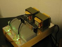
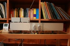
Here is how she turned out. I opted to use my salvaged transformers and build a regulated PS. Everything went pretty smooth until I started testing it and the left channel of my wife's ipod went out and decided to have a 1200 mV bias on the left channel while playing nearly at full tilt. This caused the left channel to be offset at 29 v and quickly destroyed the LM3875. I shut it down quickly enough that the speaker survived unscathed. It took a bit of time after that to figure out the ipod was the culprit.
Nothing a quick digikey order and a new ipod can't fix. I seem to be back in business now. I have to say, I'm really quite impressed with the bass control of these little chips.
Attachments
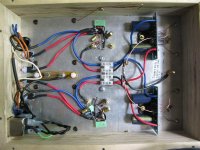
Here's an inside view.
Power supply wiring has changed since this picture was taken. The fuse is now before the switch. The IEC ground can be seen on the bottom left. The copper wire on the side of the amp grounds the top of the amp to the bottom.
Rails read +/- 30.7
Power supply wiring has changed since this picture was taken. The fuse is now before the switch. The IEC ground can be seen on the bottom left. The copper wire on the side of the amp grounds the top of the amp to the bottom.
Rails read +/- 30.7
Attachments
i start to build a LM4780 parallel mode.
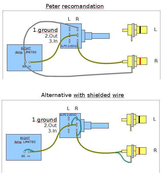
Input signal cable will get very close to the transformer in my layout. I was recomented to use shielded cable.
two options
1) recomended by Peter (use SG as star ground)
2) my suggested alternative with shielded cable
any opinion about my wiring proposal ? any other suggestion ?
Input signal cable will get very close to the transformer in my layout. I was recomented to use shielded cable.
two options
1) recomended by Peter (use SG as star ground)
2) my suggested alternative with shielded cable
any opinion about my wiring proposal ? any other suggestion ?
Hi,
the Signal Ground is an input to the amplifier.
Either use a twisted pair for the input
or
a shielded twisted pair
or
take all your shields back to Star Ground, with only one end of each shield connected to SG.
Any comment on any of the proposals?
the Signal Ground is an input to the amplifier.
Either use a twisted pair for the input
or
a shielded twisted pair
or
take all your shields back to Star Ground, with only one end of each shield connected to SG.
Any comment on any of the proposals?
in other words, you dont like my alternative proposal. ok, ;-)
i'll go for the twisted pair with no shield.
if i have interference issues, i'll use a shielded twisted pair. It will be easier.
i'll go for the twisted pair with no shield.
if i have interference issues, i'll use a shielded twisted pair. It will be easier.
Hi,
finally after more than 1 year I purchased the Audiosector kit I (almost) completed my two monoblocks with a passive pre for input selection and volume control.
I built the amp following the instruction in this thread.
I am very satisfied with the results and this amp replaced my commercial integrated amp (YBA Integre).
I reported here a low level RF noise tha is now almost gone away with the connection to the passive pre (previously I was using an Ipod directly connected to the amps).
The pre-amp is working fine with the CD player and with the turntable. On the contrary I got a noise of the same level of music when I connected the pre to my Mac Powerbook laptop head-phone output.
My Mac is working nice when I connect it to a chipamp integrated amp I built for training before building my "reference" monoblock.
Have you any idea why this malfunctioning with the laptop?
I am now a little bit afraid to try again the connection with the amp, I really would not like to damage something.
Thank you again for this great thread
Renato
- Home
- More Vendors...
- Audio Sector
- Commercial Gainclone kit- building instructions