my RCA is direct ground to chassis.
Elsewhere in this thread Peter suggests insulated RCA. I am a newbie, but I guess that with your RCAs you completely change the grounding with respect to what suggested by Peter
Renato
There is nothing to worry about grounds. Some guidance was given here: http://www.diyaudio.com/forums/showthread.php?postid=1108820#post1108820
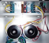
The RCAs need to be isolated from a chassis. You are using what looks like Cardas RCAs, they should come with plastic isolation washers.
I would suggest rotating transformers to minimize wire lengths.
If you are adding source selector and potentiometer, please see this diagram: http://www.diyaudio.com/forums/showthread.php?postid=1516297#post1516297
The ground does not go through selector, but does through potentiometer: RCAs --> pot --> SG on amp board
I would suggest rotating the transformers to minimise hum and buzz injected into the amplifying circuits. Then cut the connecting cables to length.Peter Daniel said:I would suggest rotating transformers to minimize wire lengths.
Remember to twist the flow and return wire pairs. This applies to mains and LV power and audio cables.
If there is a third wire to a pair, (eg. +ve, -ve, Zero Volts) then all three need to be twisted together.
AndrewT said:I would suggest rotating the transformers to minimise hum and buzz injected into the amplifying circuits. Then cut the connecting cables to length.
You may try that too, but in my experience, in a chassis like that, the hum caused by transformers is not an issue.
Hi Peter,Peter Daniel said:You may try that too, but in my experience, in a chassis like that, the hum caused by transformers is not an issue.
you are probably right.
It is worth experimenting just in case the thick aluminium is fighting against a strong field pointing in the wrong direction.
troubleshooting PD LM3875 Kit
My amp gets extremely hot and the transformer seems to vibrate a little and of course no sound. I rechecked the wiring and looked for shorts and things seem ok
I measured the voltage on PG+ V+ PG- V- and I think I found my problem since the voltage was about 36 volts and the transformers is 250 VA and is supposed to put out 25 volts.
My problem (I think) is I have 0V -> AC1 and 25V -> AC1 and the same for AC2 on my rectifier board but it should be 0V -> AC1 0V -> AC1
25 V - AC2 25V -> AC2
Is this right I wanted to make sure before I changed it and blew something up
Tom
This link shows how to connect dual secondaries transformer to rectifier board: http://www.diyaudio.com/forums/attachment.php?s=&postid=1508798&stamp=1210694958
On AC1/AC1 and AC2/AC2 you will be able to measure AC voltage only.
If transformer produces 25V AC, you will get approx 36V DC between PG+ and V+
On AC1/AC1 and AC2/AC2 you will be able to measure AC voltage only.
If transformer produces 25V AC, you will get approx 36V DC between PG+ and V+
Peter Daniel said:This link shows how to connect dual secondaries transformer to rectifier board: http://www.diyaudio.com/forums/attachment.php?s=&postid=1508798&stamp=1210694958
On AC1/AC1 and AC2/AC2 you will be able to measure AC voltage only.
If transformer produces 25V AC, you will get approx 36V DC between PG+ and V+
OK so I think I am ok coming out of the rectifier. My kit had two rectifier boards but from the forum it seems that one might work better so I am using 1
Another thought I had was that I ran a wire from the CHG hole on each amp board to my star ground. I do not have anything from my rectifier to star ground since I thought it would go through the amp boards.
So my problem must be in the amp boards. I used the continuity check on my multimeter to look for shorts. I thought the chips may have been shorted to the heatsink but I checked the pins to ground and nothing except for the 2 pins with the resister shows a connection to ground.
I have been using an old 8 ohm 1 watt speaker as a load
Any thoughts on where to look next?
Indeed, with single transformer I recommend a single rectifier board shared between two channels. Only CHG pads connect to chassis, nothing from rectifiers. There shouldn't be any star ground outside the amp boards, see more info here: http://www.diyaudio.com/forums/showthread.php?postid=1518369#post1518369
Please see this link how to measure for correct PS voltage: http://www.diyaudio.com/forums/showthread.php?postid=1518288#post1518288
If that checks out fine, the next thing you should do is to measure DC offset from the amp: http://www.diyaudio.com/forums/showthread.php?postid=1521304#post1521304
When offset measures OK, the chip most likely works fine, if there is still no sound, your wiring may be a problem.
Hi ,
I am building two monoblocks out of Peter's kit.
The design is rather complicated and thus the Ps is in a different box underneath the amp box.
The Ps box has its top made out of 1 mm copper plate, its bottom also and one of its side. The rest is wooden.
The amp box at the top has its bottom 1cm thick copper and the rest is wooden. So actually between the ps box and the amp box there some copper and air.
Peter do you think there might be a humming problem in the amp or i need more shielding? Keep in mind i will use good quality components and cables.
I know the question is theoretical but i have to do it since the design of the box is rather unique and difficult and it would be difficult afterwards for changes.
thanx
Nick
n volume is completely down (input shunted to ground).Peter Daniel said:Indeed, with single transformer I recommend a single rectifier board shared between two channels. Only CHG pads connect to chassis, nothing from rectifiers. There shouldn't be any star ground outside the amp boards, see more info here: http://www.diyaudio.com/forums/showthread.php?postid=1518369#post1518369
Please see this link how to measure for correct PS voltage: http://www.diyaudio.com/forums/showthread.php?postid=1518288#post1518288
about 36 volts I have capacitors but this seems high to me
If that checks out fine, the next thing you should do is to measure DC offset from the amp: http://www.diyaudio.com/forums/showthread.php?postid=1521304#post1521304
quote:
<<< This particular amp (right channel) measures 32mV offset when volume is completely down (input shunted to ground). >>>
I assume this means simply short the center of the RCA jack to ground?
quote:
<<< and 70mV when volume is at the maximum (15K combined input impedance of 50k pot and 22k input shunt resistor) >>>
No pot on mine I can connect preamp or output from soundcard
or do I just short a resistor to ground from the center of the rca jack, if so what resistor?
When offset measures OK, the chip most likely works fine, if there is still no sound, your wiring may be a problem.
QuoteThis particular amp (right channel) measures 32mV offset when volume is completely down (input shunted to ground).
tiglitosa said:
Peter do you think there might be a humming problem in the amp or i need more shielding?
The shielding is not always a must. In fact, I'm still using an amp without any shielding at all, boards and transformer simply mounted to an aluminum bar: http://www.diyaudio.com/forums/showthread.php?postid=636580#post636580
There is no humming issues present at all. Of course, that will depend on your local conditions.
tbrooke said:
n volume is completely down (input shunted to ground).This particular amp (right channel) measures 32mV offset when volume is completely down (input shunted to ground). Quote
So what else is there that it does not play?
Previous Post
Sorry my previous post got garbled with the quotes.
Basically I was unclear about measuring DC offset without a pot.
Tom
Sorry my previous post got garbled with the quotes.
Basically I was unclear about measuring DC offset without a pot.
Tom
To measure offset you don't need to shunt the input, as you already have the 22k R2 resistor there. That will show the highest offset, if you shunt the input, the offset will go down.
The average values measured for batch of chips were posted here: http://www.diyaudio.com/forums/showthread.php?postid=1524877#post1524877
The average values measured for batch of chips were posted here: http://www.diyaudio.com/forums/showthread.php?postid=1524877#post1524877
speaker ptotection
Hi again
Can you guys tell me how many of you are using some kind of speaker protection and does it really need to be used in gainclone?
Hi again
Can you guys tell me how many of you are using some kind of speaker protection and does it really need to be used in gainclone?
Troubleshooting revisited (LM3875)
I set up my DC offset measurements as follows
No Pot - Input to ground -
measured at speaker terminals - no load
Right - oscillates between 6 and 7 mV
Left - oscillates between 5 mV 36 mV
I can hear the transformer humming in time with the oscillations
rechecked pg+ and pg- both about 36 volts and fairly constant
rechecked wiring about 10 times
- Home
- More Vendors...
- Audio Sector
- Commercial Gainclone kit- building instructions