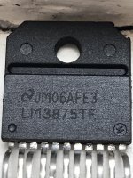
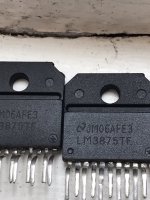
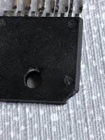
I’ve never seen engraving on those chips, the lettering was always paint: white originally and champagne colour after they switched to lead free. Also, if they new, they shouldn’t have any solder on the leads.
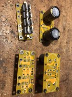
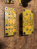
Here is my variation of Peters GC. LM3875 chips are missed - cant find genuine ones))). Boards are tiny and looks very cool.
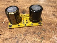
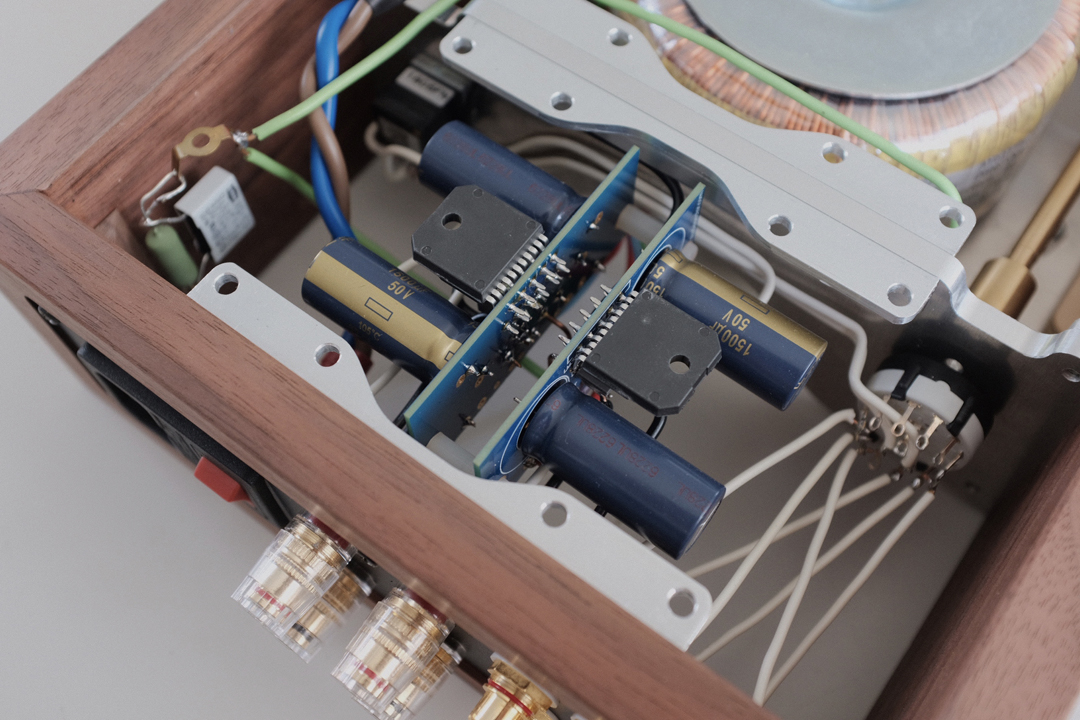
NFB resistor (Thin Film SMD Resistor, 0.1% 25ppm) is located right between IC pins 3 and 8 for the shortest ossible loop. Capacitors are 2200uf @50V Nichicon KG Gold Tune.
NFB resistor (Thin Film SMD Resistor, 0.1% 25ppm) is located right between IC pins 3 and 8 for the shortest ossible loop. Capacitors are 2200uf @50V Nichicon KG Gold Tune.
Attachments

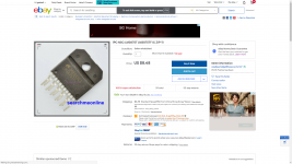
I know ebay is the last place to look for electronic components but these look real to me, before you buy ask the seller to send actual component picture and then you buy, if the component looks different then you can ask for money back.
1PC NSC LM3875T LM3875TF IC ZIP-11 | eBay
1PC NSC LM3875T LM3875TF IC ZIP-11 | eBay
Attachments
Thank you asuslover. I sent message to seller. Unfortunately, nowdays genuine 3875 become difficult to find.
Peter, are you still around here? I sent a couple of emails via your webpage, but didn't receive any reply.
Measuring DC Offset of my DAC
Hi. I really want to build an Audio Sector Gain clone Kit.
How would I use it?
I have built a raspberry Pi streamer connected to a DAC, streaming FLAC files from a plex server. This is where I need a power amp. Volume is set via rotary encoder on the DAC. Speakers will be small bookshelf 8 ohm (diy) and it will be used at moderate volumes
After reading 228 pages of this thread 😱. I am worried about a few things.
One of these things I read about is DC Offset. Although I've built a few amp kits and speakers in the past ...successfully... I know very little about electronics. So can someone confirm I am reading the DC offset of the output of the DAC correctly.
I tested both left and right output RCA's. The positive lead of the DMM on the center of the RCA and the negative lead to the ring of the RCA. I found it hard to keep the DMM probes still on the RCA surface so used the probes on the solder where they connected to the PCB (surface mount).
I tested both left and right with music playing and without, and also at the end of RCA audio cable. No amp is connected to the analog output RCA's.
I can test music IS playing from the headphone output of the DAC but all measurements were taken without headphones connected as they wont be used.
Below is a photo of the DMM. Am I reading this correctly as 0.9 mV DC?

The left channel reads 00.9 and the right reads 01.0, whether the volume is up or down. Sometimes I got measurements of 00.4 to 01.4 but mostly the measurements where as previous.
With the music stopped or muted (from the streamer), both the left and right read -00.0.
If I connect 1 Metre long RCA cables (cheap ones in my workshop I wont be using in real life) I get DC measurements of -00.9 left and -01.0 right whether volume is up or down.
So have I measured DC offset and read the DMM correctly.?
And does that mean then this offset will be ok with the LM 3875 Kit as per Peters minimal recommendations without the optional components?
Hi. I really want to build an Audio Sector Gain clone Kit.
How would I use it?
I have built a raspberry Pi streamer connected to a DAC, streaming FLAC files from a plex server. This is where I need a power amp. Volume is set via rotary encoder on the DAC. Speakers will be small bookshelf 8 ohm (diy) and it will be used at moderate volumes
After reading 228 pages of this thread 😱. I am worried about a few things.
One of these things I read about is DC Offset. Although I've built a few amp kits and speakers in the past ...successfully... I know very little about electronics. So can someone confirm I am reading the DC offset of the output of the DAC correctly.
I tested both left and right output RCA's. The positive lead of the DMM on the center of the RCA and the negative lead to the ring of the RCA. I found it hard to keep the DMM probes still on the RCA surface so used the probes on the solder where they connected to the PCB (surface mount).
I tested both left and right with music playing and without, and also at the end of RCA audio cable. No amp is connected to the analog output RCA's.
I can test music IS playing from the headphone output of the DAC but all measurements were taken without headphones connected as they wont be used.
Below is a photo of the DMM. Am I reading this correctly as 0.9 mV DC?
The left channel reads 00.9 and the right reads 01.0, whether the volume is up or down. Sometimes I got measurements of 00.4 to 01.4 but mostly the measurements where as previous.
With the music stopped or muted (from the streamer), both the left and right read -00.0.
If I connect 1 Metre long RCA cables (cheap ones in my workshop I wont be using in real life) I get DC measurements of -00.9 left and -01.0 right whether volume is up or down.
So have I measured DC offset and read the DMM correctly.?
And does that mean then this offset will be ok with the LM 3875 Kit as per Peters minimal recommendations without the optional components?
Last edited:
Thanks for the answer. Can you tell me if (by my description) I tested the offset and read the DMM correctly?
Hi Peter.
I ordered the 3875 kit last week and I'm putting together an order of other parts ill need.
I cannot find thee power LED you mention here.
Will this LED do?
If so what resistor should I buy to match still the 62K?
Also on specifying resistors...please excuse my ignorance...should I assume a metal film type is correct?
what about:
1.Tolerance
2.Power Rating
3.Voltage Rating.
I'm fine with all the sockets and wire etc and will follow your guide explicitly, but apart from the led and resistor, are there any other electronic components that aren't in the kit that I will need?
Any LED will do. Just start with higher value resistor (60k is a good start) and adjust the brightness to your preference. You may end up with 20k or even less.
As to resistors, anything will work here, don’t worry about specs, those are meaningless here. The wattage of resistor should be 1/2W or more.
As to resistors, anything will work here, don’t worry about specs, those are meaningless here. The wattage of resistor should be 1/2W or more.
Hi Everyone,
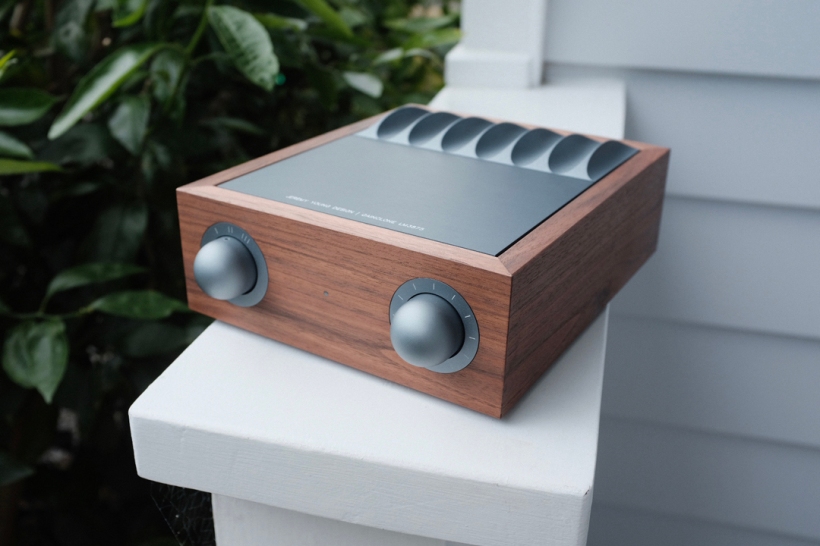
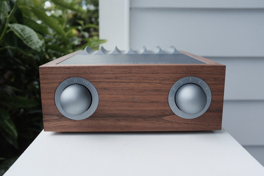
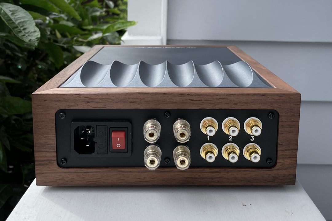
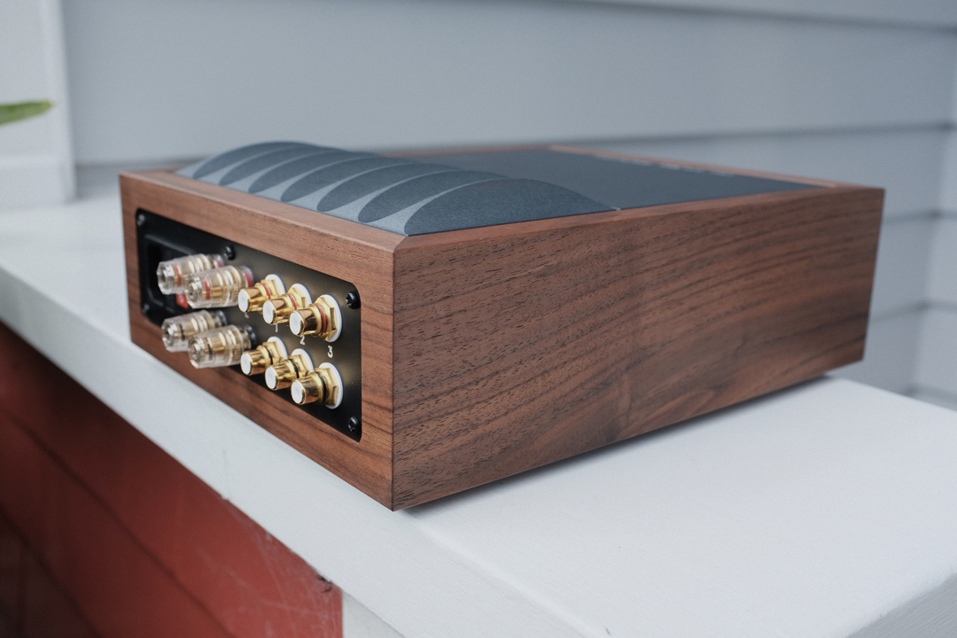
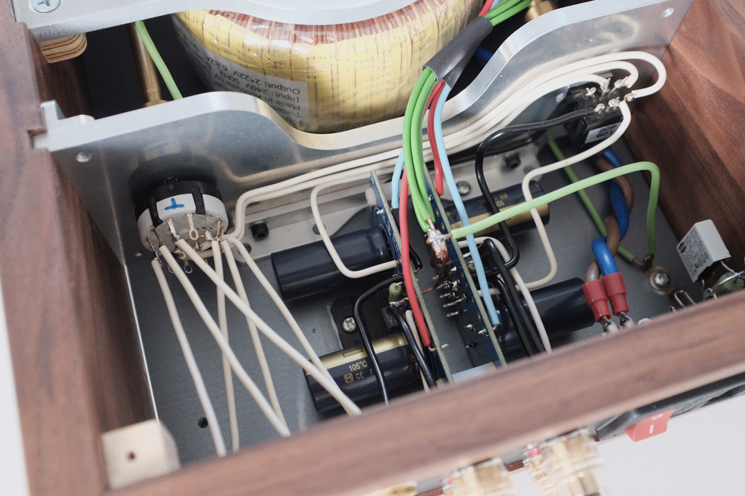
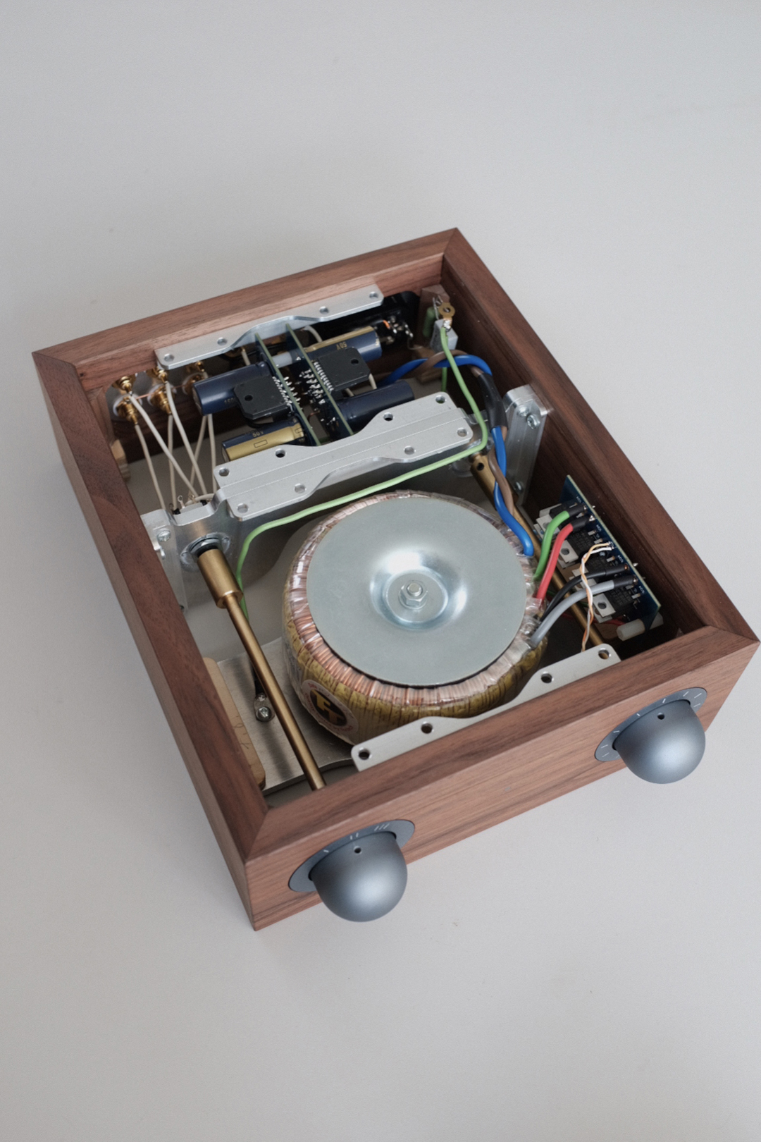
This is my Gainclone build using Peter's excellent PCBs.
I'm really happy how it came together in the end and it sounds really great.
More info on my blog if you are interested. www.jeremyyoungdesign.com
This is my Gainclone build using Peter's excellent PCBs.
I'm really happy how it came together in the end and it sounds really great.
More info on my blog if you are interested. www.jeremyyoungdesign.com
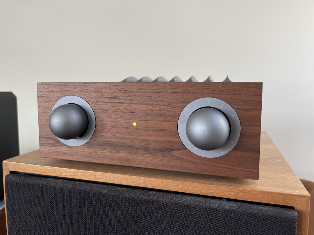
This came out really, really nice.
One of the best builds I’ve seen so far.
Thanks Peter, I appreciate the kind words.
I did email you with a question regarding the amp but you may have missed it.
I have been testing with a pair of Spendor SP1 speakers which have a sensitivity of 87 dB/W and it sounds great. I am finding that I need to turn the volume up quite high to get decent volume (1-2 o'clock position), I'm not sure if it just doesn't have quite enough power or perhaps my choice of potentiometer isn't ideal? It is a TKD CP600 50k, which apparently has a slightly unusual "ladder type log curve" according to the data sheet.
Do you have any experience with this? Perhaps I should try a lower value pot, this particular one also comes in 10kohms.
Cheers,
Jeremy
- Home
- More Vendors...
- Audio Sector
- Commercial Gainclone kit- building instructions