No need to balance any bias currents, just use 1K for R3 and keep everything else the same.
Thanks Peter!
Short follow-up question:
If I were to increase R1, would that require any bias balancing? I was simply looking at this from a standard op amp perspective, perhaps incorrectly.
/M
I got a 3875 standard kit and was wondering if I could use some 1000uF Panasonic caps instead of the provided ones that are 2700uF. I saw in the opening posts that C1/C2 were specified to 4.7uF-100uF and wanted to know what lead to higher capacitance in between back then and today.
Ragards, Stefan
Ragards, Stefan
Yes, no problem using 1000uF Panasonic caps.
C1/C1 are not recommended to be used any longer.
The main caps, Panasonic FC 1500/50, are sometimes on backorder, and then I need to substitute them with something else not to further delay order shipment.
Some people tried those 2700uF Chemicons in the past and claimed they sounded better then stock caps.
I wondering if it would be possible to build a 3 channel power amp without a volume control to be used with a surround preamp?
or are there better suited amps for this?
Matthew
or are there better suited amps for this?
Matthew
Yes, no problem using 1000uF Panasonic caps.
C1/C1 are not recommended to be used any longer.
The main caps, Panasonic FC 1500/50, are sometimes on backorder, and then I need to substitute them with something else not to further delay order shipment.
Some people tried those 2700uF Chemicons in the past and claimed they sounded better then stock caps.
Hi,
I'm in the process of building a second LM3875 kit right now; Hope you have time for a few questions:
- Should I now leave C1/C2 empty, not even use the 10uF caps?
- How would you recommend adding more capacitance nowadays if need be, only directly on the amp board?
- Is there any downside to mounting the led on the psu board since it is only driven by one of the rails, any risk for asymmetry between the rails somehow?
/M
I wondering if it would be possible to build a 3 channel power amp without a volume control to be used with a surround preamp?
or are there better suited amps for this?
Matthew
If 50W/channel is enough, it would be hard to find better amps for your application.
Yes, leave those empty, or if you like, put some small caps there and listen if it makes any difference.
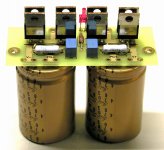
You can install big caps on rectifier board as per attached pic.
No problem with LED being powered from one of the rails.
My ambition is to make this one better in terms of hum and noise. I am improving the wiring and ground handling significantly this time around. What should I do to improve hum and noise and achieve a more 'black' background?
Can the cap selection on the rectifier board and amp board somehow be made to improve this?
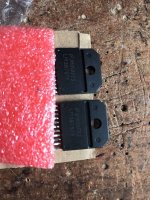
Ok, so I tried to build an stereo amp based on Peters kit and unfortunately I'm afraid that for whatever reason I have fried one of my chips, One of the channels went up in smoke for whatever reason and the smell and the sparks came from the chip. I have no idea if I can source another chip, but I would be interested to know if anybody would make an educated guess as to what went wrong:

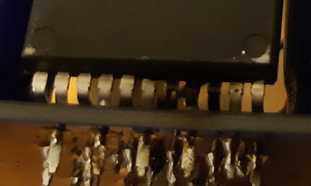
On the back one can see the 3 black coloured pins of the chip
Thank you,
Stefan
On the back one can see the 3 black coloured pins of the chip
Thank you,
Stefan
Last edited:
On the channel that did not went up in smoke I measure 25V on input and on output with nothing connected to the amp - can that be ?!? Somehow I am seriously puzzled by this project of mine. P.S.:I did not use any insulation when fixing the chips to the aluminum profile used as cooling.
LM4780 Amplifier
I've built these modules but need heat sinks. Can anyone suggest an appropriate heat sink and source?
Thank you.
I've built these modules but need heat sinks. Can anyone suggest an appropriate heat sink and source?
Thank you.
On the channel that did not went up in smoke I measure 25V on input and on output with nothing connected to the amp - can that be ?!? Somehow I am seriously puzzled by this project of mine. P.S.:I did not use any insulation when fixing the chips to the aluminum profile used as cooling.
No need for insulation when mounting the chip, as the case is self insulating plastic package.
It could go in smoke because the supply voltage was reversed, or you had some sort of short circuit? Can you post picture of your rectifier board?
25V at the input could be caused by bad solder joints or resistors mixed up?
I just recently found this site, and been reading about this kit.
Would this be a good kit to mod an existing speaker set into a couple active speakers, primarily used as keyboard monitor ? since its designed as a mono block.
Also where would I find info about using 2 in either paralell or bridged mode ?
Would this be a good kit to mod an existing speaker set into a couple active speakers, primarily used as keyboard monitor ? since its designed as a mono block.
Also where would I find info about using 2 in either paralell or bridged mode ?
Yes, it would be perfect kit for that.
For parallel or bridge mode LM4780 is preferred. The info can be found here: Kit arrived
For parallel or bridge mode LM4780 is preferred. The info can be found here: Kit arrived
Yes, no problem using 1000uF Panasonic caps.
C1/C1 are not recommended to be used any longer.
The main caps, Panasonic FC 1500/50, are sometimes on backorder, and then I need to substitute them with something else not to further delay order shipment.
Some people tried those 2700uF Chemicons in the past and claimed they sounded better then stock caps.
Do you mean that C1 and C2 on the rectifierboard no longer are required?
If so for what reason and should i remove them from my assembled kit ?
Kind regards
Edwin
I've been successfully using AudioSector LM3875 kits for several years with stepped attenuator VCs but would now like to re-site the amps, shorten the perhaps over-long speaker leads and use longer leads between the VC and the amps.
The snag is that, when I try longer signal leads, the amps oscillate in an, er, lively manner. I'm reasonably sure a buffer circuit would fix the issue but I'd prefer (also) to try and fix the oscillation.
The signal leads use a quad-core geometry that, as you know, is rather more capacitive than alternatives. I omitted the 1K input resistor R1; the SA's serial resistor in on the low side (5K6). (I accept that low-value resistors do not help stability but the amps' sound quality is noticeably better than it is with higher values.)
Any suggestions as to what I might do?
TIA,
Dave
- Home
- More Vendors...
- Audio Sector
- Commercial Gainclone kit- building instructions