whats the purpose of a 0.1uf cap on the psu board. Are these supposed to be close to the BR or the bulk caps or the output socket?
I would rate the star ground circuit as substantially worse then the common ground one (But neither are ideal), the problem is that you seem to be treating opamps as 3 terminal devices when they are really 5 terminal ones.
Consider for a moment the current flowing at the output of the audio circuit, and consider a time when the opamp is sourcing current from the positive rail, now, that current has to flow in a loop back to the positive supply pin of the opamp by some means... In the star ground circuit thus is via node B and some combination of the supply caps and node C (Via the decoupling caps), that is a lot of loop area.
In your ground bus based design the loop is simply via the decoupling caps, job done (But 10uF or so of elco across each of those 100n bypasses will get you substantially lower THD at low frequency).
My favorite approach is something of a hybrid, use a ground plane for the decoupling caps and be smart about where I connect audio reference nodes to the ground plane. For example R1,3,& 5 as well as the input and output could all be netted together and tied down to the plane at one location, which means that only audio current would flow in that net.
Planes (And monster copper pours) are your friends...
It is possible to get all kinds of complicated about grounds (and this is, for the most part, an audio disease), you just don't see it anywhere else, and plenty of other places deal with signals that are MORE delicate then line level audio.
Regards, Dan.
Bentsnake, you have gone from bad to worse. There are still several problems. For one, Vcc+ and Vee- are not a feed-and-return pair. Is it so difficult to do a current analysis?
It improves the high frequency response of the supply. Beter near the caps.
Gajanan Phadte
If I am using 3 sets of caps, which end would you put this 0.1uf cap at, near the large caps close to the rectifier or near the large caps close to the output socket?
Don't add parallel caps to the PSU smoothing electrolytics. This bad practice can make oscillation worse.
If you add any caps, then they must be snubbers, i.e. a cap+resistor to damp out the oscillation.
If you add any caps, then they must be snubbers, i.e. a cap+resistor to damp out the oscillation.
Moving on:
a] The AC power Safety Ground/Protective Earth should only connect to the Power Supply chassis near the IEC connector. The Power Supply to Audio Circuit Chassis Bond jumper should only be chassis to chassis (no internal wires) and it should be near the Op-Omp supply cable.
b] The Circuit Ground Bus should exit and enter the chassis's through the same aperture as the Op Amp Power twisted pair and should remain in close proximity to the twisted pair.
c] It should be the main Circuit Ground Bus that connects to the chassis near the input jacks (not a jumper).
Actually, no. You do not share ownership of another's published material because you took a picture of it. Duplication of another's published material is for the most part frowned upon by the legal system.Yes that's true, if you believe that Mr. Self's circuits jumped out of his book, transformed themselves into .jpg images, and posted themselves to the Internet.
Otherwise, yes the circuits are his, but the images are mine. Which is to say we share ownership.
If you are presenting a portion of the material in order to teach, then that can be allowed as long as you are not impacting the author's ability to earn; there are allowances for that within the law.
It is nice to see that you are attributing the work to the author, that shows class. I thank you for that.
Since Mr. Self is a contributor to this forum, I assume he is aware of your copying and is comfortable with it. Perhaps you should drop him a line, introduce yourself, and mention what you have done and why. That would be a reasonable courtesy.
I must point out however, that ground loop and hum concerns are all about control of the current path. The ideal signal transfer mechanism is one where the signal cable, when cross-sectioned, presents zero net current. Coax, twisted pairs used properly do this. The second issue is that of ground topology creating a conductive loop which traps time varying magnetic field from the local environment.
jn
whats the purpose of a 0.1uf cap on the psu board.
Solder Ca across the terminals of Cc, Cb across the terminals of Cd, and look here: Decoupling capacitor - Wikipedia, the free encyclopedia
.
You do not share ownership of another's published material because you took a picture of it.
Nor do I claim to. Again, the circuits are his, but the images are mine.
.
If you add any caps, then they must be snubbers, i.e. a cap+resistor to damp out the oscillation.
Snubbing everything in sight seems to have become the fashion. Fortunately, like all fashions, this too shall pass.
.
Vcc+ and Vee- are not a feed-and-return pair
Awrk. Thanks for pointing that out. They should be twisted, of course,but I need to fix the notes.
.
If I am using 3 sets of caps, which end would you put this 0.1uf cap at, near the large caps close to the rectifier or near the large caps close to the output socket?
There is no output socket on the posted schematic. But put the small caps toward the power supply output, not toward the rectifier.
Nor do I claim to. Again, the circuits are his, but the images are mine.
.
I believe this can be construed as a claim:I've bolded the part.
Otherwise, yes the circuits are his, but the images are mine. Which is to say we share ownership.
You cannot "share" ownership of another's published material, not a facsimile, not a picture, not a hand drawn duplicate, not an image.
You can use part of his material as long as it falls under the fair use clause. I believe that may have been your intent all along.
I'm only cautioning you as to what your verbage meant to me.
jn
You cannot "share" ownership of another's published material
Nor do I claim to. Yet again, the circuits are his, but the images are mine.
You'll forgive me if I consider this subject closed. There's actual work to do, y'know.
.
Nor do I claim to. Yet again, the circuits are his, but the images are mine.
You'll forgive me if I consider this subject closed. There's actual work to do, y'know.
.
You may choose to act as an ostrich with respect to copying work of others and claiming you own the image.. that is no problem for me. No matter what you choose to ignore, you still do not "share" ownership of the content with Doug as you claimed earlier... That is all I've been cautioning you about.
Actual work to do. Ok. Let's talk about grounding schemes. (like, ""y'know"", what I do for a living..)😀
Ground control is all about control of the path of the current.
High impedance circuitry works best with star grounds.
Low impedance circuitry requires control of current paths, with all currents tied intimately between send and return, such that magnetic field is minimized.
Low signal circuitry requires careful control of loop area such that external time varying magnetic field cannot be loop trapped.
Devices which have more than one port require careful consideration and control of the current at each port. Well designed devices will have at the input port, ONLY the input currents. The output port will ONLY have output currents. The supply port will carry ONLY supply currents.
When EMC considerations are neglected by design and fabrication, current can travel port to port, and that compromises the hardware.
I note a statement given earlier, I believe by Andrew...that a wire in a time varying magnetic field environment will have a voltage produced on it. That by itself, is an inaccurate statement. If for example, that wire is a hollow conductor, like a shield, there will be no induced voltage between that shield and the core wire contained within. Until one attempts to connect a measurement wire to the end of that shield, there is no voltage. The loop formed by a measurement wire and that shield is what traps magfield and creates a voltage potential difference..
If I chose the core wire as my measurement wire, then I would see no voltage at the end of the shield.
Rather than posting schematics and saying "this solves ground loop", or "how can one eliminate ground loop", you would be better off actually building the hardware, then taking pictures of it and posting it here. In that way, we could actually discuss where the loops are and what they are trapping. I've some ground loop content on my gallery, you're welcome to peruse it and ask questions if you wish. I've also some neat tests for detecting ground loop sensitivity as well.
BTW, adding caps willy nilly as bypass can indeed create resonances in the rf range, Andrew is correct here in that some resistance is also needed should the circuitry be susceptible to rf, such as that created by some rectifiers in supplies or line noise coming in the IEC.
jn
Last edited:
Awrk. Thanks for pointing that out. They should be twisted, of course,but I need to fix the notes.
.
If they are not a current pair what is the point of twisting them?
If they are not a current pair what is the point of twisting them?
Agreed. The only way that would be effective is if there is output transistor cross conduction. That will not zerofield any output load currents.
The load return current needs to be "twisted" with both rails to remove rail loops.
I wrote "twisted", because a triax will work as well, also a 3 layer stripline construct with the return current in the center and rails to either side. Personally, I'd make the stripline center as three side by side, with the opamp input ground reference as the center one, the load return as the outer two.
R. Marsh did this several decades ago IIRC.
jn
.
Many thanks to those commenting on the posted circuit. A hiatus while I carefully study these, along with others that might be posted.
Not including comments about loop area. Loop area does not appear on schematics, as I'm now officially tired of pointing out. If you want to talk about loop area, then post a parts layout so you'll be talking about something that exists.
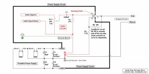
Meanwhile, the below posted might be amusing. It's intended to show that any audio circuit consists of three current loops (NOT loop areas). They are:
1. The power supply loop. Theoretically the op amp is unaware of the power supply. As far as the op amp is concerned there's just a source of infinite current at a given voltage.
2. The audio circuit loop. Ideally the op amp is also unaware of the audio input circuit. It's only aware of a voltage change at the sensing point, in this case terminal three.
3. The output circuit loop, which is the one currently under consideration.
Interestingly, the output circuit does not exist until the op amp creates it. That is, at zero volume the output circuit is just a collection of wires, it has no electrical significance until there's an output from the op amp. To create an output the op amp valves (hence the term) a controlled amount of power into the output circuit.
This is interesting because it speaks to current return. At zero volume the large power supply conductors carry only the small current necessary to run the op amp, perhaps 10 millamps.
But as a for-instance, a 20 watt amp running at 20 volts must return a full one amp to the power supply (watts = volts x amps, so amps = watts / volts). This doesn't sound like much until you realize that it's 100 times the current running the op amp.
This points up why current return must be considered. If the input and output signals were perfectly clean, and in phase, it wouldn't matter. But of course no signal is perfectly clean, and the op amp itself introduces a phase shift, so mixing the output back into the input will inevitably result in distortion.
Admittedly this brings up the eternal question: does it matter? Phase distortion, for instance, is subtle, and it remains a fact that any given amp is far, far more accurate than any given speaker. So whether it matters might be a matter of taste. But still, why introduce distortion on purpose?
.
Many thanks to those commenting on the posted circuit. A hiatus while I carefully study these, along with others that might be posted.
Not including comments about loop area. Loop area does not appear on schematics, as I'm now officially tired of pointing out. If you want to talk about loop area, then post a parts layout so you'll be talking about something that exists.
Meanwhile, the below posted might be amusing. It's intended to show that any audio circuit consists of three current loops (NOT loop areas). They are:
1. The power supply loop. Theoretically the op amp is unaware of the power supply. As far as the op amp is concerned there's just a source of infinite current at a given voltage.
2. The audio circuit loop. Ideally the op amp is also unaware of the audio input circuit. It's only aware of a voltage change at the sensing point, in this case terminal three.
3. The output circuit loop, which is the one currently under consideration.
Interestingly, the output circuit does not exist until the op amp creates it. That is, at zero volume the output circuit is just a collection of wires, it has no electrical significance until there's an output from the op amp. To create an output the op amp valves (hence the term) a controlled amount of power into the output circuit.
This is interesting because it speaks to current return. At zero volume the large power supply conductors carry only the small current necessary to run the op amp, perhaps 10 millamps.
But as a for-instance, a 20 watt amp running at 20 volts must return a full one amp to the power supply (watts = volts x amps, so amps = watts / volts). This doesn't sound like much until you realize that it's 100 times the current running the op amp.
This points up why current return must be considered. If the input and output signals were perfectly clean, and in phase, it wouldn't matter. But of course no signal is perfectly clean, and the op amp itself introduces a phase shift, so mixing the output back into the input will inevitably result in distortion.
Admittedly this brings up the eternal question: does it matter? Phase distortion, for instance, is subtle, and it remains a fact that any given amp is far, far more accurate than any given speaker. So whether it matters might be a matter of taste. But still, why introduce distortion on purpose?
.
Attachments
You repeated what I posted well enough.
Now,
Look at your drawing very carefully. Note you have two rails and the load return current drawn as 3 independent entities. You have drawn loops as you indicate.
The output must be intimate with the load return from the load to the amp. Your drawing does not indicate such.
At the amp, the load return must be intimate with BOTH rails. Your drawing does not show that either.
The amp reference ground needs to be considered as well for loop trapping. There is nothing on the drawing to indicate this.
Draw in methods to control those loops, then let's discuss.
jn
- Status
- Not open for further replies.
- Home
- Source & Line
- Analog Line Level
- Comment on Grounding Scheme?