Google search "loop areas"
http://www.ultracad.com/articles/loop.pdf
rf - loop area and EMI - Electrical Engineering Stack Exchange
EMC Tip 13 - The impact of loop areas on radiation and immunity
This last one could help in finding additional loops.
http://www.ultracad.com/articles/loop.pdf
rf - loop area and EMI - Electrical Engineering Stack Exchange
EMC Tip 13 - The impact of loop areas on radiation and immunity
This last one could help in finding additional loops.
Thanks for posting that diagram, it certainly is...colorful.
Now if you'll please point out how it relates to some problem you see in the circuit I posted, I'll be grateful.
.
You are beyond help.
It depends on what you mean by "work". If you mean "will it produce a DC output of around the right value" then yes it will work. If you mean "will it avoid injecting hum and buzz into the audio signal" (which presumably is what most grounding questions relate to) then no it might not unless you also take account of the magnetic induction issue we have been raising.bentsnake said:The present issue is problems/not, that is, will it work in the first place?
When someone posts a circuit and asks about one aspect of that circuit (in this case, grounding details) it is quite common for people to helpfully point out other aspects of the circuit and its implementation which are relevant. Some people find this unhelpful and complain if we do it. Other complain if we don't do it!
To achieve a quiet amp correct grounding is necessary, but it is not sufficient.
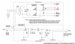
They mean this. I had to draw over some of your capacitors to make it obvious, but you get the idea; the wires which carry ripple current should be bundled together to minimise the area of the charging loop. Also, try to keep the transformer, rectifier and reservoir caps in close proximity, as this also keeps the loop as small as possible:
Thanks for your post, Mrelinb, yes I do get the idea.
Even if the idea does seem a bit off kilter. If you're right, as I believe you are, then all of this fracas has basically been over twisted pairs. Or that is to say, good wiring practice, or in the case of printed circuit boards good layout.
I personally think these are subjects unto themselves, not something you'd usually go into on a schematic. But in any case not to worry. When the context calls for it I'll certainly quote according to your clarification, and thanks again for posting.
.
Bentsnake, I thought you were trying to teach us how to produce a good layout,
Promoting a layout that transmits EMI into the audio circuit is not a problem?
Promoting a layout that transmits EMI into the audio circuit is not a problem?
When someone posts a circuit and asks about one aspect of that circuit (in this case, grounding details) it is quite common for people to helpfully point out other aspects of the circuit and its implementation which are relevant. Some people find this unhelpful and complain if we do it. Other complain if we don't do it!
Damned if you do, damned if you don't. And ain't that the way of it?
Meanwhile, a revision. As always I hope for corrections. But I think the subject of twisted pairs has been pretty well covered.
.
Attachments
Any ground differentials between equipment will cause an earth loop and you will get hum with those scheme.
Either use a ground lifter, or use a ground interconnect decoupling resistor.
Either use a ground lifter, or use a ground interconnect decoupling resistor.
Any ground differentials between equipment will cause an earth loop and you will get hum with those scheme.
Will you please say what would be a better scheme?
.
Ive posted a link to a document that would help you make amplifers that suffer from no hum. Read it, and then take another look at your proposal.
Any ground differentials between equipment will cause an earth loop and you will get hum with those scheme...Ive posted a link to a document that would help you make amplifers that suffer from no hum.
Sorry, I just can't see the "ground differentials between equipment" that you refer to. Would you please clarify by pointing out the problem in the posted circuit, and how it's corrected in the circuit you linked to?
.
A wire placed in a varying magnetic field will have a varying current imposed along it.
The inherent impedance of that length of wire will react to that current and show a varying voltage difference between the two ends.
This is science.
Use the science to help avoid hum problems.
A twisted pair is a very effective way of canceling the effects of that interference voltage in the Flow and Return Pair.
Insert Loop into that Flow and Return Pair and the science tells everyone that there will be an interference voltage imposed on the circuit from every interference field in that locality.
To put it in perspective, its quite easy to end up with mA of ground loop current in an interconnect shield - you will get hum from that.
Rule 1 is twist the 'to' and 'from' wires tightly together (see the 'colorful' drawings in my link)
Rule 2 - make sure ground loops cannot form. In your diagram, you connect the incoming ground to the chassis, and then connect the output retrun to the star ground and then also have the main earth connection going to the chassis.
You are going to have loop currents all over the place with that, and every chance that they will flow in the interconnect return (usually the shield).
Use a ground lifter between the chassis and the star ground (see slide #2 on my articale on how to do this safely) and use a 15~22 ohm 'decoupling' resistor in the between the input ground on the amplifer board and the ground return. This works exceedingly well because the usual ground resistances are a fews 10's to 100s of mOhms. So with the resistor in place, the ground currents will prefer to flow in the equipment earth connections and not along your shield.
A wire placed in a varying magnetic field will have a varying current imposed along it....(etc)
Yes we all agree on that, and you've posted it several times before.
Will you please indicate where on the posted schematic you see a problem?
.
I am still trying to sort the charging circuit.
Sort that before I move on to the other errors.
The routing the cables need to follow has been described.
Sort that before I move on to the other errors.
The routing the cables need to follow has been described.
I am still trying to sort the charging circuit.
Sort that before I move on to the other errors.
Sort things out is exactly what I'm trying to do. But if you won't point out where on the posted schematic you see an error, then how do you think that could be possible?
I'm simply asking that you indicate where on the posted schematic any error might be. Everything is labeled, so simply indicate, that's all I'm asking.
.
...In your diagram, you connect the incoming ground to the chassis, and then connect the output retrun to the star ground and then also have the main earth connection going to the chassis.
You are going to have loop currents all over the place with that, and every chance that they will flow in the interconnect return (usually the shield)...
Thanks for this post, it seems we're making progress at last.
But no, the "main earth ground" (point A) does not connect to the chassis. Or not directly, which is what you seem to mean. So taking this into account can you please re-state to clarify?
Or else, if I'm not getting your meaning, will you say how the connections you speak of should be made?
.
I had a few questions about all this.
The usual 10/22 uf charging cap for opamp and 0.1uf decoupling cap to be treated same, combine their ground and return a single line?
all decoupling caps (for both the rails for multiple opamps?) can be wired together and brought as a single line to the grounding point?
I guess its a good idea not to merge signal ground with the decoupling ground before bringing to the star ground. Run a separate line to star from audio ground on the amp pcb to the star ground on the psu pcb? I assume the star ground point is the 0V output at the psu pcb.
why connect input ground to chassis.
About twisted wires, for trafo to psu pcb, twist all three together? from psu pcb to amp pcb, twist all three together? Audio return from amp pcb to psu pcb goes solo?
I had a few questions about all this.
The usual 10/22 uf charging cap for opamp and 0.1uf decoupling cap to be treated same, combine their ground and return a single line?
all decoupling caps (for both the rails for multiple opamps?) can be wired together and brought as a single line to the grounding point?
I guess its a good idea not to merge signal ground with the decoupling ground before bringing to the star ground. Run a separate line to star from audio ground on the amp pcb to the star ground on the psu pcb? I assume the star ground point is the 0V output at the psu pcb.
why connect input ground to chassis.
About twisted wires, for trafo to psu pcb, twist all three together? from psu pcb to amp pcb, twist all three together? Audio return from amp pcb to psu pcb goes solo?
Excellent questions. I've asked them myself. No kidding.
This is a building project, not something I claim is "right." At bottom I'm trying to come up with something that will answer the newbie's inevitable question, "How am I supposed to connect all these ground thingees together?" Come up with something simple enough to be usable, I should say.
Bearing that in mind, my best information at this time is:
<< The usual 10/22 uf charging cap for opamp and 0.1uf decoupling cap to be treated same, combine their ground and return a single line?...all decoupling caps (for both the rails for multiple opamps?) can be wired together and brought as a single line to the grounding point? >>
The ideal would be to run all decoupling cap lines individually. But with several op amps in a circuit this can get ridiculously complicated, so my thinking is run them to a bus reserved for decoupling caps.
<< I guess its a good idea not to merge signal ground with the decoupling ground before bringing to the star ground. Run a separate line to star from audio ground on the amp pcb to the star ground on the psu pcb? I assume the star ground point is the 0V output at the psu pcb. >>
If I understand your question, star ground (point B) might be 1/4" away from circuit ground (point B) or several inches. Or several feet for that matter.
Run all the audio returns to a point that you define as star ground. This point is probably on the amp (not power supply) board. Then run a single conductor from there to circuit ground, which is on the power supply board.
One star ground and one only, there can't be one for the audio circuit, and another for the power supply. Nor would there be, since the star point is for audio only.
<< About twisted wires, for trafo to psu pcb, twist all three together? from psu pcb to amp pcb, twist all three together? >>
The custom I'm aware of is to twist all 3 together. I have suspicions about the math of this, but everybody seems to do it and it probably doesn't hurt anything.
<< Audio return from amp pcb to psu pcb goes solo? >>
Goes to the single star ground, which as above is probably on the amp board.
<< why connect input ground to chassis >>
The best question of all, and one I've wrestled with. Quoting from Douglas Self's "Audio Power Amplifier Design Handbook," page 402:
"Mains/chassis ground will need to be connected to the power amplifier at some point. Do not do this at the transformer centre-tap as this is spaced away from the input ground voltage by the return charging pulses, and will create severe groundloop hum when the input ground is connected to mains ground through another piece of equipment.
"Connecting mains ground to starpoint is better, as the charging pulses are excluded, but the track resistance between input ground and star will carry any ground-loop currents and induce a buzz.
"Connecting mains ground to the input ground gives maximal immunity against groundloops."
So the why is 'cause he says so.
If you have other ideas about any of this, or see an error I've made, I'd like very much to hear about it. Don't judge by this dialog of the moment, I'm just trying to get these guys to be specific. In the context of this thread, finding out I'm wrong is what I'm all about.
.
Last edited:
Doors666, it is probably best to draw your schematic/layout and include the current, loop and ground analysis.
- Status
- Not open for further replies.
- Home
- Source & Line
- Analog Line Level
- Comment on Grounding Scheme?