I don't know about your country but in Holland the Ground Fault Circuit Interrupter (aardlekschakelaar) would open at 30 mA of ground current.
The Class 2 regulations kind of prohibit DIY and also limits the power.
The Class 2 regulations kind of prohibit DIY and also limits the power.
Last edited:
Here in Austria a lot of older buildings do not have ground fault circuit interrupter.
EN60065 2006:
"Der Widerstand der Verbindung zwischen dem SCHUTZLEITERANSCHLUSS oder Schutzkontakt und Teilen, die hiermit verbunden sein müssen, darf nicht größer als 0,1 Ω sein. "
e.g. Resistance between PE and other parts must be less than 0.1 Ohm.
"Die Prüfung erfolgt durch folgenden Versuch:
Die Prüfung muss 1 min mit einem Prüfstrom von 25 A Wechsel- oder Gleichstrom durchgeführt werden. Die
Prüfspannung darf nicht größer als 12 V sein."
e.g Test is done with 25 Ampere for 1 minute. Voltage must be less than 12 Volt.
Thx, Udo
Way ahead of you.
Incomplete. The problem (charging spikes that mustn't contaminate the audio gnd) comes from the transformer-diodes-cap circuit, using batteries doesn't show it.
Last edited:
So if the resistance is less than 0.1 Ohm with a 25 A current and it survives 1 min, it should comply.
I read somewhere that Class 2 / Class II testing requirements include repeatedly dropping the piece of equipment on a concrete floor without failure to the equipment.
I read somewhere that Class 2 / Class II testing requirements include repeatedly dropping the piece of equipment on a concrete floor without failure to the equipment.
I don't know about your country but in Holland the Ground Fault Circuit Interrupter (aardlekschakelaar) would open at 30 mA of ground current.
The Class 2 regulations kind of prohibit DIY and also limits the power.
Here in Austria a lot of older buildings do not have ground fault circuit interrupter.
EN60065 2006:
"Der Widerstand der Verbindung zwischen dem SCHUTZLEITERANSCHLUSS oder Schutzkontakt und Teilen, die hiermit verbunden sein müssen, darf nicht größer als 0,1 Ω sein. "
e.g. Resistance between PE and other parts must be less than 0.1 Ohm.
"Die Prüfung erfolgt durch folgenden Versuch:
Die Prüfung muss 1 min mit einem Prüfstrom von 25 A Wechsel- oder Gleichstrom durchgeführt werden. Die
Prüfspannung darf nicht größer als 12 V sein."
e.g Test is done with 25 Ampere for 1 minute. Voltage must be less than 12 Volt.
Thx, Udo
ClassII requirements are onerous.So if the resistance is less than 0.1 Ohm with a 25 A current and it survives 1 min, it should comply.
I read somewhere that Class 2 / Class II testing requirements include repeatedly dropping the piece of equipment on a concrete floor without failure to the equipment.
I know I can't design, nor test, nor guarantee a ClassII build. So I don't try.
I have not seen any Member claim they are trained to design and test ClassII equipment.
On that basis we Members can ONLY design and build ClassI equipment.
The first safety requirement for ClassI equipment is that the Chassis MUST be directly connected to the Protective Earth wire in the mains cable.
There are other requirements, but that is the major one and it affects the comments being made in the last few posts.
The UK has similar clauses in the "test" of equipment to check the impedance during a fault incident.
I don't know the clauses but I think there are at least two.
One describes a test that ensures when Fault Current passes into the PE that the "Live" equipment does not exceed a specified (presumed safe) voltage.
The second describes a test that ensures the PE impedance is adequately low to allow the first test to give a reliable answer.
These involve passing a high current from the equipment Chassis through the Safety Earth into the PE of the Mains cable.
I think we also use 25A as one of the test currents.
These tests do not check for errors in the internal wiring. They just check the "escape route" for a Mains Fault.
"The metal parts of Class 1 equipment could assume a hazardous voltage if the basic insulation fails, so there is a requirement that the metal parts are earthed via the protective conductor."
How do you earth the amplifier outputs? Speaker connections are often exposed metal parts.
How do you earth the amplifier outputs? Speaker connections are often exposed metal parts.
Disconnecting Network between exposed conductive parts and the Safety Earth.
All exposed conductive parts must be connected to the protected chassis.
These parts if they become "Live" would conduct the Fault Current to the protected chassis via the "connection" from Main Audio Ground (MAG) to Chassis or via another specific route installed by the Builder. eg a wire from the metal case of an adjustment pot direct to chassis.
Some amplifiers, particularly multi-channel amplifiers, perform better if the MAG is not "wired" to Chassis. But MAG MUST still be connected to pass Fault Current to PE if any exposed part is indirectly connected to some exposed conductive part.
To enable that Fault Current to pass without a DIRECT wire connection, many suggest a power diode/rectifier as a route that passes the current and inserts an impedance between Chassis and MAG.
esp discusses this at length. He appears to have followed the extensive discussions on this Forum and then formulated a very informative article showing OUR conclusions.
I have called this circuit a Disconnecting Network.
Because it effectively disconnects the Audio side from the Safety side.
But very importantly allows Fault Current to pass to comply with "All exposed conductive parts must be connected to Chassis".
If one passes 25A through a DN, then the voltage drops will be the sum of wire resistances times test current + leadout/connector resistances times test current + Vf of the power diodes.
I use two parallel connected 25A or 35A diodes inside a bridge rectifier. (esp recommends the same parallel arrangement)
The Vf of these will be around 1V to 2V when passing that 25A.
If all the other resistances add up to 0r05, then the total voltage drop will be around 2.25V to 3.25V
This is well below the 12V quoted by Udok.
It is also well below the limiting value in the UK regulations (even though I can't remember the clauses).
As an aside:
I tested my version of the DN.
All the components (rectifier, 100nF MKT & 10r 600mW metal film) survived the Fault Current (presumed to be >>>100Apk) undamaged for the time it took to rupture the Mains Fuse.
Last edited:
You came back too soon."The metal parts of Class 1 equipment could assume a hazardous voltage if the basic insulation fails, so there is a requirement that the metal parts are earthed via the protective conductor."
How do you earth the amplifier outputs? Speaker connections are often exposed metal parts.
I said "There are other requirements," and I was writing a post about one of these other requirements.
However,
I don't believe your phrase correctly states the requirement in the UK.
"there is a requirement that the metal parts are earthed via the protective conductor".
In the UK the requirement as far as I know is for a connection to Chassis.
Do you have access to the relevant regulation Clauses for the Netherlands?
My point is that the amplifier + outputs are often 'exposed conductive parts" and can not be connected to earth.
other parts !
If a mains wire comes loose and touches a "part", then that part becomes "Live".
The amp has apparently "turned off".
There are a number of sceanarios that follow:
One gets out of one's seat and twiddles with the equipment !!!!!
One switches off at the mains, before investigating. Very unlikely.
One complains to the Forum "my equipment that you designed for me does not work"
The first is the most likely, and let's hope it's not your wife or other family member that gets there first.
For that fault, we expect the equipment to remain safe.
The easiest way is for the mains fuse to blow.
For that to happen the Fault Current must "escape".
That is why the regulations have been written.
How does the mains fault blow the fuse if "other parts" have become live?
I read somewhere that Class 2 / Class II testing requirements include repeatedly dropping the piece of equipment on a concrete floor without failure to the equipment.
There is no difference in Class II and I. From 60065 2002:
12.1.1 Bump test
Apparatus with a mass exceeding 7 kg are subjected to the following test.
The apparatus is placed on a horizontal wooden support, which is allowed to fall 50 times from
a height of 5 cm onto a wooden table.
After the test, the apparatus shall show no damage in the sense of this standard.
12.1.4 Drop test
PORTABLE APPARATUS HAVING a mass of 7 kg or less are subjected to a drop test. A sample of
the complete apparatus is subjected to three impacts that result from being dropped through a
distance of 1,0 m onto a horizontal surface in positions likely to produce the most adverse
results.
The horizontal surface consists of hardwood at least 13 mm thick, mounted on two layers of
plywood each 19 mm to 20 mm thick, all supported on a concrete or equivalent non-resilient
floor.
For each drop, the test sample shall strike the surface in a different position. When applicable,
the sample is to be dropped with the batteries specified by the manufacturer.
Upon conclusion of the test, the apparatus need not be operational, but shall withstand the
dielectric strength test as specified in 10.3, in particular:
– HAZARDOUS LIVE parts shall not have become ACCESSIBLE,
– insulating barriers shall not have been damaged, and
– CLEARANCES and CREEPAGE DISTANCES shall not have been reduced.
The test criteria shall not be applied through openings in the face of the picture tube.
12.1.2 Vibration test
TRANSPORTABLE APPARATUS intended to be used for audio amplification of musical instruments,
PORTABLE APPARATUS and apparatus having a metal enclosure, are subjected to a vibration
endurance conditioning by sweeping, as specified in IEC 60068-2-6.
The apparatus is fastened in its intended positions of use to the vibration-generator by means
of straps round the enclosure. The direction of vibration is vertical, and the severity is:
– Duration 30 min
– Amplitude 0,35 mm
– Frequency range 10 Hz ... 55 Hz ... 10 Hz
– Sweep rate approximately 1 octave/min.
After the test, the apparatus shall show no damage in the sense of this standard, in particular,
no connection or part the loosening of which might impair safety shall have loosened.
12.1.3 Impact test
The apparatus is held firmly against a rigid support and is subjected to three blows from a
spring-operated impact hammer according to IEC 60068-2-75, applied with a kinetic energy just
before impact of 0,5 J to every point of the enclosure that protects HAZARDOUS LIVE parts and is
likely to be weak, including ventilation areas, drawers in the pulled-out position, handles,
levers, switch knobs and the like, by pressing the release cone perpendicularly to the surface.
This impact hammer test is also made on windows, lenses, signal lamps and their covers, etc.,
but only if they protrude from the enclosure by more than 5 mm or if the area of the plane
projection of the individual surface area exceeds 1 cm².
Moreover, the non-ventilated solid areas of the enclosure that protect HAZARDOUS LIVE parts
shall be subjected to a single impact, specified in Table 6.
The impact specified in Table 6 shall be caused by allowing a solid, smooth, steel ball of
(50 ±1) mm in diameter and with the mass of approximately 500 g to fall freely from rest
through a vertical distance, as illustrated in Figure 8, and strike the enclosure with the specified
impact in a direction perpendicular to the enclosure surface.
After the test, the apparatus shall withstand the dielectric strength test as specified in 10.3 and
shall show no damage in the sense of this standard; in particular:
– HAZARDOUS LIVE parts shall not have become ACCESSIBLE,
– insulating barriers shall not have been damaged,
– those parts subjected to the impact hammer test shall show no visible cracks.
NOTE 3 Damage to the finish, small dents which do not reduce CLEARANCES or CREEPAGE DISTANCES below
the specified values, cracks which are not visible to the naked eye, surface cracks in fibre-reinforced mouldings and
the like are ignored.
Annex N (Routine Tests) has some more information:
N.1 Tests during the production process
N.1.3 Protective earthing connection of screens and metal barriers
For CLASS I apparatus with a screen or metal barrier (see 8.5) between HAZARDOUS LIVE parts
and TERMINALS regarded as ACCESSIBLE (see 8.4) or ACCESSIBLE conductive parts respectively,
the continuity of the protective earthing connection should be checked as late as possible
during the production process between the screen or metal barrier and
– the protective earthing contact of the MAINS plug or appliance inlet, or
– the PROTECTIVE EARTHING TERMINAL in case of a PERMANENTLY CONNECTED APPARATUS.
The test current applied for 1 s to 4 s should be in the order of 10 A a.c., derived from a source
having a no-load voltage not exceeding 12 V.
The measured resistance should not exceed
– 0,1 Ω for apparatus with a detachable power supply cord,
– 0,2 Ω for apparatus with a non-detachable power supply cord.
N.2 Tests at the end of the production process
The following tests should be made on the apparatus when completely assembled and just
before packing.
N.2.1 Dielectric strength test
The insulation of the apparatus should be checked by the following tests. In general, these
tests are considered to be sufficient.
An a.c. test voltage of substantially sine-wave form, having MAINS frequency, or a d.c. test
voltage or a combination of both with a peak value specified in Table N.1, is applied between
the MAINS supply TERMINALS connected in parallel and:
– TERMINALS regarded as ACCESSIBLE (see 8.4), and
– ACCESSIBLE conductive parts respectively,
which may become HAZARDOUS LIVE in the event of an insulation fault as a result of incorrect
assembly.
NOTE 1 TERMINALS regarded as ACCESSIBLE and ACCESSIBLE conductive parts may be connected together during
the dielectric strength test.
Table N.1 – Test voltage
Basic Insulation: 1500 Vrms (for MAINS Voltage > 150)
Double or reinfored Insulation: 2500 Vrms (for MAINS voltage > 150)
Before the test voltage is applied, intimate contact should be made with the specimen.
No flash-over or breakdown should occur during the test. The test voltage source should be
provided with a current sensing (over-current) device which, when activated, gives an indication
that the test has been failed. The test voltage source should still deliver the prescribed voltage
until current tripping occurs.
.
Yoo hoo. Anybody remember me? The poor sap who asked a question, not understanding that you need an MS in vibration mechanics before you're allowed to build a chip amp? Not that I shouldn't have known in advance. After all, a chip amp is liable to have as many as four components. Six if you count the input circuit.
Willy-nilly, I thought I'd jump back in with the latest, and also with many thanks to 00940 for helping me finally see through what previously was a blind spot.
Posted is the current state of the art...so to speak. A bit anticlimactic in its simplicity.
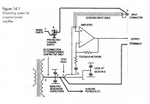
But what did you expect, no free rides. Douglas Self has evolved into the High Guru of this thread, and he states, "Rail decoupler capacitors must have a separate ground return to the Reservoir Ground. This ground must not share any part of the audio ground system, and must not be returned to the Starpoint. See Figure 14.1." (op.cit.)
All of which stands well to reason until you look at figure 14.1 (also posted), in which he cheerily returns the "local HT decouple" capacitors (H) to Star Point F.
I don't know whether Mr. Self means these HT capacitors are "local" to the power supply, or "local" to the op amp(s), and I find no clarification in the text. So I've taken the position that decoupling (or bypass) capacitors have no business being connected into the audio circuit in any case, and routed them to my point A, ground, which is Mr. Self's point E, his Reservoir Ground.
Right? Wrong? Research continues, while as before correction is implored.
Still remembering that as long as the audio signal is kept clear of power supply lines you won't be far wrong.
.
Yoo hoo. Anybody remember me? The poor sap who asked a question, not understanding that you need an MS in vibration mechanics before you're allowed to build a chip amp? Not that I shouldn't have known in advance. After all, a chip amp is liable to have as many as four components. Six if you count the input circuit.
Willy-nilly, I thought I'd jump back in with the latest, and also with many thanks to 00940 for helping me finally see through what previously was a blind spot.
Posted is the current state of the art...so to speak. A bit anticlimactic in its simplicity.
But what did you expect, no free rides. Douglas Self has evolved into the High Guru of this thread, and he states, "Rail decoupler capacitors must have a separate ground return to the Reservoir Ground. This ground must not share any part of the audio ground system, and must not be returned to the Starpoint. See Figure 14.1." (op.cit.)
All of which stands well to reason until you look at figure 14.1 (also posted), in which he cheerily returns the "local HT decouple" capacitors (H) to Star Point F.
I don't know whether Mr. Self means these HT capacitors are "local" to the power supply, or "local" to the op amp(s), and I find no clarification in the text. So I've taken the position that decoupling (or bypass) capacitors have no business being connected into the audio circuit in any case, and routed them to my point A, ground, which is Mr. Self's point E, his Reservoir Ground.
Right? Wrong? Research continues, while as before correction is implored.
Still remembering that as long as the audio signal is kept clear of power supply lines you won't be far wrong.
.
Attachments
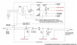

Compare D.Self to your diagram.
look very carefully at the routes D E F G and D E F H
D is the link CT to PSU Zero Volts. This MUST be a direct link. It MUST NOT be taken on a long looping journey around the amplifier.
This DE link MUST be close coupled to BOTH AC secondary wires from the transformer to the smoothing capacitors, even as it passes through the bridge rectifier.
re-post with that bit corrected and Someone will give you the next bit to remove your errors.
Last edited:
"The metal parts of Class 1 equipment could assume a hazardous voltage if the basic insulation fails, so there is a requirement that the metal parts are earthed via the protective conductor."
How do you earth the amplifier outputs? Speaker connections are often exposed metal parts.
Generally hazardous voltage parts shall not be accessible. This is the reason why modern amps do not have banana plugs anymore. And as far as i remember there is a minor exception for the speaker output terminal.
Bentsnake: Sorry for the long excerpt from the standard. It is maybe a bit too detailed for a diyaudio post.
Back to your question: Important is, that the input point A, the amplifier reference point G and the output terminal reference point have the same voltage.
If you keep this rule in mind, the rest is rather simple 🙂
Now assume that each conductor has resistance. If the three points A, G and output terminal have equal voltage then no current flows.
No current = no voltage drop = equal voltage at the three points A, G, and output terminal.
The next step is to imagine how the current in your circuit may flow. Do this for possible ground loop currents, for the rail capacitor current and other currents.
e.g. if the local rail decouple current flows through point G, this is bad, as the output voltage depends on the current through the decouple caps.
Last edited:
Compare D.Self to your diagram.
look very carefully at the routes D E F G and D E F H
D is the link CT to PSU Zero Volts. This MUST be a direct link. It MUST NOT be taken on a long looping journey around the amplifier.
This DE link MUST be close coupled to BOTH AC secondary wires from the transformer to the smoothing capacitors, even as it passes through the bridge rectifier.
re-post with that bit corrected and Someone will give you the next bit to remove your errors.
The DE link doesn't pass through the bridge rectifier. Hoping for clarification, I've re-labeled my schematic below with Mr. Self's reference points.
.
Attachments

Last edited:
YOU must route the DE link across the rectifier to minimise the LOOP AREA of the CT current and the secondary currents passing through the rectifier.
The closer the DE link to the rectifier diodes the smaller the Loop Area.
I see you have relabeled your diagram.
Make the CT connection to H, DE link is now DH link
Could you use a different colour for the DH link. That way it can pass straight across and we can see there are no electrical connections to the rectifier.
Last edited:
Bentsnake: Sorry for the long excerpt from the standard. It is maybe a bit too detailed for a diyaudio post.
Back to your question: Important is, that the input point A, the amplifier reference point G and the output terminal reference point have the same voltage.
If you keep this rule in mind, the rest is rather simple 🙂
Now assume that each conductor has resistance. If the three points A, G and output terminal have equal voltage then no current flows.
No current = no voltage drop = equal voltage at the three points A, G, and output terminal.
The next step is to imagine how the current in your circuit may flow. Do this for possible ground loop currents, for the rail capacitor current and other currents.
e.g. if the local rail decouple current flows through point G, this is bad, as the output voltage depends on the current through the decouple caps.
Only for explanatory purposes:
So you're defining the audio input as point A? A bit confusing since on my schematic point A is ground, but let's go with A = audio input, why not.
And you're defining G as circuit ground? OK. Or it's OK unless you mean the G on Mr. Self's schematic, but you don't say so I don't know.
Point "output terminal" is the audio output terminal? Power supply output terminal? I have no idea what you mean by "output terminal reference point." There is no such point on either posted schematic.
In any case, "...if the local rail decouple current flows through point G, this is bad..."
So this local (to what?) rail decouple current is not to be directed to ground, which is your point G? Then where?
And, "...the output voltage depends on the current through the decouple caps."
If you mean the power supply output voltage, then that's the output voltage of the bridge rectifier, it has nothing to do with any capacitors anywhere.
If you mean the audio output voltage, then of course no it doesn't.
Sorry, I simply have no idea what you're talking about.
If you're actually talking about either or both of the posted schematics, it would probably make things clearer if you referred to those.
.
I assume he is referring to Fig 14.1 in post 37. Point A is the ground reference for the input. Point G is the ground reference for the feedback network. These two points need to be at the same potential, otherwise the feedback network is not just sensing the difference between input and output (as it should) but also the difference between A and G. By 'output voltage' I assume he means the signal output voltage from the power amp, which will be affected by decoupling ground currents if these are allowed to pollute point G.
The point he is making is that every connection has impedance, so if you want two different points to have the same potential then you have to ensure that no current flows along the path between them.
The point he is making is that every connection has impedance, so if you want two different points to have the same potential then you have to ensure that no current flows along the path between them.
- Status
- Not open for further replies.
- Home
- Source & Line
- Analog Line Level
- Comment on Grounding Scheme?