YOU must route the DE link across the rectifier to minimise the LOOP AREA of the CT current and the secondary currents passing through the rectifier.
The closer the DE link to the rectifier diodes the smaller the Loop Area.
I see you have relabeled your diagram.
Make the CT connection to H, DE link is now DH link
Could you use a different colour for the DH link. That way it can pass straight across and we can see there are no electrical connections to the rectifier.
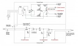
For clarity, I'm yet again posting my re-labeled schematic. This is the only schematic I'm referring to in this post.
If I at all understand what you're saying, which I might not, you want to run a wire from point D (the center tap of the transformer), up over BR1, and down to point E? I have to disagree, I can see no possible point in doing that.
Are you, perhaps, concerned about the physical length of conductor D-E? Not to worry, in the real world this conductor is quite short, schematics are not drawn to scale.
Additionally, if I understand, you advise that circuit ground be the junction between Ca and Cb?
Again I have to disagree. Typically Ca and Cb are very small ceramic capacitors, often soldered directly to the terminals of Cc and Cd. In my view not at all a wise choice for the ground point.
Then again, if Ca/Cb are, in fact, soldered to the terminals of Cc/Cd, then point E and the Ca-Cb junction are the same point, so it's a non-issue.
.
Attachments
Sounds like you are back to your non-listening mode.
I said said "minimise LOOP AREA".
I described how to reduce that Loop Area.
Why do you think many of us are talking about Loop Area?
Then you come up with
I said some Members would come along and sort all the other errors.
Don't sidetrack this first change, loop area from Transformer to smoothing capacitors.
Sort it, then hear what we have to say about the rest.
I said said "minimise LOOP AREA".
I described how to reduce that Loop Area.
Why do you think many of us are talking about Loop Area?
Then you come up with
LOOP AREA is the "point" !I can see no possible point in doing that.
I said some Members would come along and sort all the other errors.
Don't sidetrack this first change, loop area from Transformer to smoothing capacitors.
Sort it, then hear what we have to say about the rest.
Last edited:
What will happen in your proposal if there is a differential between the earths of of the device shown, and the source?
Self's scheme BTW is not without its problems, and assumes all equipment is well earthed (as it should be) but does not deal with what happens if earth loop currents flow on the return screen of the interconnects.
- follow the advice and minimize loop area wherever possible.
-'T' off to avoid injecting common impedance coupled charging current I*R drops into the amplifer circuitry
- if you can, recitify and smooth the secondaries independently and then combine them (costs an additional rectifier)
- a ground lifter can work wonders - especially where there may be ground differentials between equipment
- use a low value (15~22 Ohms) decoupling resistor in the signal ground of the input of the amplifer. This forces any ground circulating currents to flow through the chassis earth connections and not the interconnect cables (the potenial problem with Self's implementation)
- for RF, dont forget to couple the incoming ground at the connector to the chassis directly with a 1nF ceramic cap - works wonders
- a snubber across each secondary (1K and 1nF) will also reduce diode switching noise - a problem in some arrangements.
I dont mind admitting in my younger days I struggled with this . . . . my stuff sometimes hummed like a buzz saw, and other times through sheer luck, was quiet.
Getting wiring in a power amp or preamp 'right' takes time and effort before one can develop an intuitive feel for the practice.
No grounding scheme is perfect . . . but I sure as hell am building some quite equipment these days 😀
Last edited:
Sounds like you are back to your non-listening mode.
I said said "minimise LOOP AREA".
I described how to reduce that Loop Area.
😀😀😀😀😀😀😀😀!
.
<< What will happen in your proposal if there is a differential between the earths of of the device shown, and the source? >>
The same thing that happens with any proposal. The short A-B spur is the significant difference in this circuit, can you see it causing grounding problems?
<< follow the advice and minimize loop area wherever possible >>
Would that one could. But so far only the vague "minimize loop area" admonition has been offered. No specific problem has been pointed out, and no specific solution has been offered. If you can see a problem, will you please clarify?
<< a ground lifter can work wonders >>
It can also land you in court, civil, criminal, or both. I have no legal expertise, but here's a for-instance, one of many that Google will show: https://hub.yamaha.com/percussion/21842-ac-power-considerations-with-your-front-ensemble
.
post44 is yet another misleading diagram that many here keep telling you is wrong.
Either listen as you claim you want to do, or remove all these very many misleading diagrams from all the many Threads where you have posted them..
Either listen as you claim you want to do, or remove all these very many misleading diagrams from all the many Threads where you have posted them..
It is not that vague. The problem is magnetic induction, which is proportional to loop area at both ends. The charging loop (from secondary, via rectifiers, to reservoir caps) carries sharp pulses, so you don't want that inducing voltages into signal loops. Keeping loops small, and well apart, reduces this problem.bentsnake said:But so far only the vague "minimize loop area" admonition has been offered. No specific problem has been pointed out, and no specific solution has been offered. If you can see a problem, will you please clarify?
post44 is yet another misleading diagram that many here keep telling you is wrong.
"Many" seems to be pretty much you. Again I ask: will you please identify the specific problem you're referring to? And can you offer a solution?
.
It is not that vague. The problem is magnetic induction, which is proportional to loop area at both ends. The charging loop (from secondary, via rectifiers, to reservoir caps) carries sharp pulses, so you don't want that inducing voltages into signal loops. Keeping loops small, and well apart, reduces this problem.
Yes, I'm afraid it is vague, in that advice to "minimize loop area" applies to every circuit in the world.
If there's any specific problem having to do with the posted circuit--the one supposedly under discussion--I sure would like to hear what it is.
.
Take a look here
How to wire-up a Power Amplifier_Updated | hifisonix.com
This incorporates most of what the experienced commentators have been telling you. Note the twisted wires.
And no, correctly executed ground lifters are quite safe and will not land you in court.
How to wire-up a Power Amplifier_Updated | hifisonix.com
This incorporates most of what the experienced commentators have been telling you. Note the twisted wires.
And no, correctly executed ground lifters are quite safe and will not land you in court.
It does apply to every circuit in the world - or even the universe. However, magnetic induction falls off quite quickly with distance so you can safely ignore circuits whose distance away is significantly larger than their typical dimensions. Sorry, "significantly larger" may be a bit too vague.bentsnake said:Yes, I'm afraid it is vague, in that advice to "minimize loop area" applies to every circuit in the world.
If you want precision then you will need to use a full EM field simulation.
Take a look here
How to wire-up a Power Amplifier_Updated | hifisonix.com
This incorporates most of what the experienced commentators have been telling you. Note the twisted wires.
Thanks for posting that diagram, it certainly is...colorful.
Now if you'll please point out how it relates to some problem you see in the circuit I posted, I'll be grateful.
.
It does apply to every circuit in the world - or even the universe. However, magnetic induction falls off quite quickly with distance so you can safely ignore circuits whose distance away is significantly larger than their typical dimensions. Sorry, "significantly larger" may be a bit too vague.
If you want precision then you will need to use a full EM field simulation.
The precision I ask is that you relate your comments in some way to the posted circuit. Hopefully pointing out a problem, and ideally offering a solution. If so inclined, would you please do this?
.
Last edited:
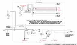
I described how to route the transformer CT to smoothing cap wire.
you rejected that so I answered withlook very carefully at the routes D E F G and D E F H
D is the link CT to PSU Zero Volts. This MUST be a direct link. It MUST NOT be taken on a long looping journey around the amplifier.
This DE link MUST be close coupled to BOTH AC secondary wires from the transformer to the smoothing capacitors, even as it passes through the bridge rectifier.
YOU must route the DE link across the rectifier to minimise the LOOP AREA of the CT current and the secondary currents passing through the rectifier.
The closer the DE link to the rectifier diodes the smaller the Loop Area.
I described one correction. you ignored that.so far only the vague "minimize loop area" admonition has been offered.
I pointed out the first problemNo specific problem has been pointed out,
and described how to remove the error.and no specific solution has been offered.
I have and still you reject alleging that Andrew T is the only Member who can see YOUR errors.If you can see a problem, will you please clarify?
Last edited:
I am unclear what you are asking for, which has not already been provided. We have said that loop areas need to be minimised. We have said why (magnetic induction). We have given an example of a particularly important loop (the charging pulse loop) which appears in your circuit and said how to optimise it. As far as I can see, we have pointed out a problem and offered a solution. These comments relate to the circuit you posted. Could you be less vague about what it is you feel we have not delivered?bentsnake said:The precision I ask is that you relate your comments in some way to the posted circuit. Hopefully pointing out a problem, and ideally offering a solution. If so inclined, would you please do this?
I am unclear what you are asking for, which has not already been provided. We have said that loop areas need to be minimised. We have said why (magnetic induction). We have given an example of a particularly important loop (the charging pulse loop) which appears in your circuit and said how to optimise it. As far as I can see, we have pointed out a problem and offered a solution. These comments relate to the circuit you posted. Could you be less vague about what it is you feel we have not delivered?
<< We have said that loop areas need to be minimised. >>
I think there must be agreement here. But could you please point out where in the posted circuit a loop area problem occurs?
<< We have given an example of a particularly important loop (the charging pulse loop) which appears in your circuit and said how to optimise it. >>
Optimization is desireable, of course, but not the present issue. The present issue is problems/not, that is, will it work in the first place?
After all, there's no use trying to optimize something that doesn't work. So again, could you please point out the problem with, in this instance, the charging pulse loop in the posted circuit?
I'd suppose that the purpose of posting a reply in these forums is to answer a poster's question about a specific circuit. Otherwise, if just stating some general principle like "minimize loop area" is considered to be an answer, then you could as well answer all questions with "E=IR" and let it go at that.
.
I described how to route the transformer CT to smoothing cap wire.you rejected that so I answered withI described one correction. you ignored that.I pointed out the first problem and described how to remove the error.I have and still you reject alleging that Andrew T is the only Member who can see YOUR errors.
This all seems to boil down to, "If you don't get it then tuff luck bubba."
Well...er...fine. Perfectly OK with me if that's your view.
.
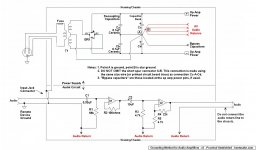
They mean this. I had to draw over some of your capacitors to make it obvious, but you get the idea; the wires which carry ripple current should be bundled together to minimise the area of the charging loop. Also, try to keep the transformer, rectifier and reservoir caps in close proximity, as this also keeps the loop as small as possible:<< We have said that loop areas need to be minimised. >>
I think there must be agreement here. But could you please point out where in the posted circuit a loop area problem occurs?
.
Attachments
Last edited:
- Status
- Not open for further replies.
- Home
- Source & Line
- Analog Line Level
- Comment on Grounding Scheme?