Thanks JanFredholm. I understand S1 to S4. But from my understanding the L12 is the axial length of horn. So i think it should start at the mid point of S1 and go to the midpoint of S2. Is this right ? Correct me if i am wrong .
Hi Buzzy,
look at page 15 in "Help" files for Hornresp.
Begun to edit the default horn and name it and take away the old values and make a tapped horn.
in "HELP " it says wery clear that L12 is measured from closed hornthroat to center of driver diapraghm ,thoat side.
It also says that L23 is the lenght of the horn ,measured between throatside of diapraghm to the mouthside of diapraghm.
It also says that L34 is the lenght between center of mouthside of diapraghmand the horn mouth.
As in my "fast" plan´s and others more refined schematic´s
Just do as it says in "Help" .
Make a "tryout" so you can learn the program by doing better and better curves, as you can see in "SPL response".under "window".
you can put alot of "0" below the values for the driver.
And you must put a larger value on s2 than s1 and a larger value on s4 thans3. then you can double click on the L12,23,34 and the program helps you. and when you have put in values where the program ask for it you have a "tools" box with a "tapped horn wizard" that make everything for you at a start.
good luck/ J😕
Till very recently you were absolutely right, just to make things more complicated: This is a screenshot made with Hornresp 16.40 😉And you must put a larger value on s2 than s1 and a larger value on s4 thans3.

Wkr Johan
Higher Frequencies?
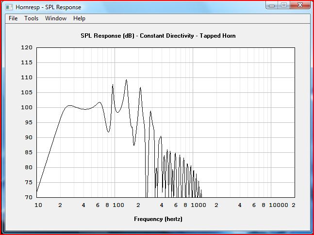
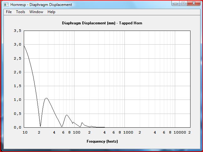
Does it make sense to use a tapped horn for higher frequencies? I can simulate to get about 102dB (2.83V) out of a small horn in the range 90-300Hz.
Here's the script I used:
| Based on 30 Hz Tapped Horn (script adapted from William Cowan's Website, http://diy.cowanaudio.com/)
Def_Const |Horn Dimensions
{
a1 = 230e-4; |Area at throat (cm^2)
a2 = 240e-4; |Area at rear of driver (cm^2)
a3 = 800e-4; |Area at front of driver (cm^2)
a4 = 900e-4; |Area at mouth (cm^2)
l1 = 10e-2; |Distance from throat to rear of driver (cm)
l2 = 90e-2; |Line distance from rear of driver to front of driver (cm)
l3 = 10e-2; |Distance from front of driver to mouth (cm)
}
Def_Driver 'Dr1'
| 18sound 10MB400
Sd=350cm2
fs=70Hz
Qes=0.37
Qms=3.5
Vas=41L
Re=5.1ohm
Le=1.05mH
system 'S1'
Driver Def='Dr1' Node=1=0=3=4
Waveguide 'W1' Node=2=3 STh={a1} SMo={a2} Len={l1} Conical
Waveguide 'W2' Node=3=4 STh={a2} SMo={a3} Len={l2} Conical
Horn 'H1' Node=4 STh={a3} SMo={a4} Len={l3} Conical
Any help appreciated! Cheers!
I considered putting a midrange in a tapped horn for my Unity clones. I can't see why it wouldn't work. I opted for bandpass mids instead of tapped horn mids because the mouth of the tapped horn was too big.
Hi Patrick,Patrick Bateman said:I considered putting a midrange in a tapped horn for my Unity clones. I can't see why it wouldn't work. I opted for bandpass mids instead of tapped horn mids because the mouth of the tapped horn was too big.
please explain, were you fitting a mid driver to the bass horn or a separate mid horn with dedicated mid driver?
If mid driver to mid horn then the mouth should be roughly the same as the mid Sd or upto twice Sd.
AndrewT said:
Hi Patrick,
please explain, were you fitting a mid driver to the bass horn or a separate mid horn with dedicated mid driver?
If mid driver to mid horn then the mouth should be roughly the same as the mid Sd or upto twice Sd.
This was a unity horn -
In a Unity horn the mids are basically in a bandpass enclosure which is coupled to the rest of the horn. To complicate matters further, they are NOT located at the apex of the horn! Confusing huh?
Only way to model a Unity horn is with Akabak. I've never seen anyone post an Akabak model though. Back when I was doing my Unity, I hadn't discovered Akabak. If I had six months to myself, I'd love to create a Unity horn model. That would be a heck of a project!
Sabbelbacke said:Once again, hornresp ist updatet. Thanx 🙂
@david
BTW, what did you improve this time?
Hi Sabbelbacke,
Version 16.40 allows mass-loaded horns and negative conical flares to be modelled. Note 6 on page 15 of the Help file refers.
Kind regards,
David
Hi David - - does that mean Hornresp 16.40 can now examine the following arrangement cases?
Best, Freddy
Best, Freddy
An externally hosted image should be here but it was not working when we last tested it.
I´d guess no (if you interpred your design as tapped horn), since tapped hornes are seen as a horn consisting of three parts where the driver is "tapped" between 1-2 and 2-3. Your design could be seen as a vented enclosure with a widening port. This, of course is possible with hornresp for quite some time. AjHorn is also able to do the trick. Try looking for "MTL", or "hybrid" designs (at least in Germany these are found under these terms).
freddi said:Hi David - - does that mean Hornresp 16.40 can now examine the following arrangement cases?
Best, Freddy
Hi Freddy,
Unfortunately, no. While it is certainly possible to enhance the tapped horn model to account for the abrupt reduction in cross-sectional area part way along the main horn segment, I am reluctant to do this as significant changes would need to be made to the program to allow the required configuration to be specified.
Sabbelbacke's comments are also relevant.
Kind regards,
David
Although I read through most of this thread it remained unlear for me why TD's TH's work with the driver installed this far away of the mouth/throat of the horn. When I tried hornresp simulations with TH's in similar configurations the results were very bad.
Same as for the other builders here, my simulations only looked well with the driver sitting "inside the mouth and firing directly into the throat.
May this be related to the so assumed higher stiffness of the cone suspension TD's driver has got?
Can somebody comment on that?
One other question for me is how well a required lowpass for the TH works since there is usually a large increase in efficiency at the upper end uf the usual response. Do you guys have experience on this?
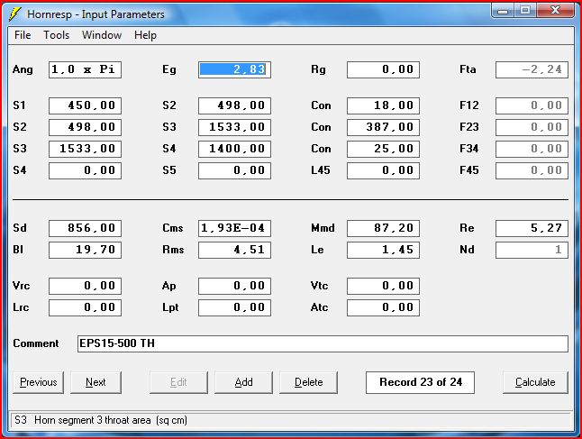
Currently I think about building a TH of approx. 440cm in length. I have two 15" lying around: One is a car sub (Next CL15 with low fs) the other is an obsolete Eminence (EPS15-500 more xmax)
Driver SD Cms Mmd Re BxL Rms LE Fs Vas Qes Qts Qms Xmax
cm² mm/N g Ohm NxA mH Hz l mm
Next CL15 824 0,31 168 3,2 13,5 3,81 2,58 22 325 0,41 0,38 6,12 15
EPS15-500 856 0,193 87,2 5,27 19,7 4,51 1,45 38,8 199 0,29 0,27 4,72 6,3
The CL15 needs a larger throat but the response of the Eminence is ruler flat from 25 to 70Hz.
I'll post the sims within the next days.
Erik
Same as for the other builders here, my simulations only looked well with the driver sitting "inside the mouth and firing directly into the throat.
May this be related to the so assumed higher stiffness of the cone suspension TD's driver has got?
Can somebody comment on that?
One other question for me is how well a required lowpass for the TH works since there is usually a large increase in efficiency at the upper end uf the usual response. Do you guys have experience on this?
Currently I think about building a TH of approx. 440cm in length. I have two 15" lying around: One is a car sub (Next CL15 with low fs) the other is an obsolete Eminence (EPS15-500 more xmax)
Driver SD Cms Mmd Re BxL Rms LE Fs Vas Qes Qts Qms Xmax
cm² mm/N g Ohm NxA mH Hz l mm
Next CL15 824 0,31 168 3,2 13,5 3,81 2,58 22 325 0,41 0,38 6,12 15
EPS15-500 856 0,193 87,2 5,27 19,7 4,51 1,45 38,8 199 0,29 0,27 4,72 6,3
The CL15 needs a larger throat but the response of the Eminence is ruler flat from 25 to 70Hz.
I'll post the sims within the next days.
Erik
I also have a pair of EPS 15-500 here currently working in a vented enclosure. Looking forward to your design 🙂
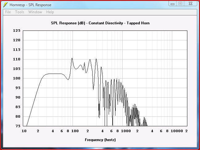
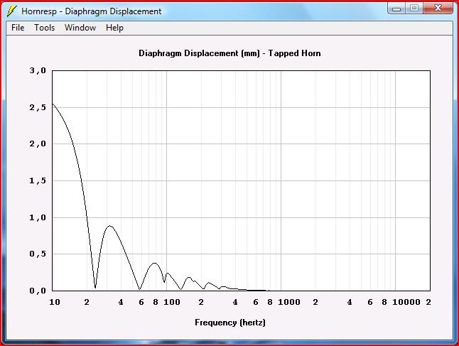
Here are the sims of the Eminence speaker:
These are the ones of the Car Subwoofer:
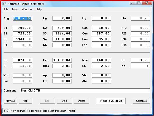
Note that Both TH's have the same length and mouth but the car sub needs a much larger throat to have an even response.
Which one would you give a try?
TIA.
Erik
These are the ones of the Car Subwoofer:
Note that Both TH's have the same length and mouth but the car sub needs a much larger throat to have an even response.
Which one would you give a try?
TIA.
Erik
I´d go for the eminence, since it`s smaller and still has more Power (the car sub is a 4 Ohm type, change the input voltage to 2 Volt instead of 2,83 Volt for the 8 Ohm Eminence).
Didn´t think that these old babys would work so well, I have to fire up my hornresp and Abakab 🙂
Edit: Oh I just saw that you don´t seem to have a straight line, right? Did you straighten the three segments with the wizard?
Edit2: Aah, the second flare is negativ conical.... Didn´t update my hornresp..... have to...
I changed the sims of the Next car sub to have an input voltage of 2,00.
Actually, I prepared a small Excel spreadsheet to calculate the input parameters for Hornresp to have an even rise in area throughout the length of the horn.
I did not jet figure out what the wizard is about.
Erik
Actually, I prepared a small Excel spreadsheet to calculate the input parameters for Hornresp to have an even rise in area throughout the length of the horn.
I did not jet figure out what the wizard is about.
Erik
Volvotreter said:Although I read through most of this thread it remained unlear for me why TD's TH's work with the driver installed this far away of the mouth/throat of the horn. When I tried hornresp simulations with TH's in similar configurations the results were very bad.
Same as for the other builders here, my simulations only looked well with the driver sitting "inside the mouth and firing directly into the throat.
May this be related to the so assumed higher stiffness of the cone suspension TD's driver has got?
Can somebody comment on that?
I think it really depends on the ts parameters of the driver you use. If one driver is far away from the mouth, it behaves as if it would be a driver with a stronger motor which is nearer to the mouth. The peak around the lower cutoff gets a higher Q with a stronger motor. The same happens if you make the part of the horn between driver front and mouth longer. So, if the driver is placed deep in the horn like the dts20, it will have a rather weak motor system.
If you set S1, S4 and the three segment lengths and run the wizard it will give you an even rise.Volvotreter said:I did not jet figure out what the wizard is about.
Equally if you want to move the driver you start the wizard and enter 2 of the section lengths, the third will be calculated under the assumption that overall horn length is the same.
- Home
- Loudspeakers
- Subwoofers
- Collaborative Tapped horn project