Hello All,
This might be becoming an interresting project. Whitin two months i am going to start with a new sawdust project - trying to make a tapped horn.
I am using a new driver from beyma, called 15P1200ND. It`s one of the newer designs of beyma. Because this driver has a stiff suspension it`s becoming very usefull in a tapped horn enclosure.
I have maked a simulation off a 4-pack labhorns against a 4-pack tapped horns. Driving the tapped horns each with 85V rms (whitout taken the heatfactor) levels of 150dB can be hit at the mouth of the horn (-6dB for 1mtr). You could see this is very close to a 4-pack of labhorns IF the labhorns can be driven that hard, because when you look at the excursion plots you notice that the tapped horns aren`t exceeding it`s xmax (1,1cm) and the labhorns going well above their excursion limits.
I am going build this project totally from the ground up.
That means;
- making an enclose over the backside of the driver, measuring it.
- slaming it against the sidewall of the horn, measuring it.
- modificate the horn (if not satisfied), measuring it.
- making the real folding horn.
So you see it`s gone be a lot of sawdust and i think it will take almost a half year.
Cheers,
Marcel
http://img503.imageshack.us/my.php?image=excurck8.jpg
http://img503.imageshack.us/my.php?image=frequw3.jpg
Best Tamas.
I am also really not convinced that Akabak predictions does not show the real excursion. Recently i post a subject about this on the PSW forum, but didn`t get any reply so i stucked for the moment.
One fact is:
The excursion of a diagram in an acoustic network is;
Volume velocite / (2*Pi*Hz*Sd). When taking an example of the 4-pack labhorns at 30Hz and 85V RMS, it`s RMS excursion is;
2,92m3/s / (2*Pi*30*(8*0,0506)) = 38,2MM RMS.
Akabak is really presenting this value when driven with 85V RMS, but akabak is talking about a peak value and this also something what i does not understand, because it`s volume velocite is also an RMS value.
Beside`s what`s right, the advantage of the tapped horn over the labhorns can be seen.
What or your thought about the excursion plots.
Interesting topic
Cheers,
Marcel
Hi Marcello,
My measurements of excursion are peak to peak values!!!
I will attach here the excursion graph for 4 LABsub halfspace at 85Vrms based on my AkAbak modell...
You will see, this is very near to my measured Xcursions, but mainly below 40Hz there is a big difference! (Akabak shows nearly double Xcursion than in reality around 30 Hz)
Btw. the Tapped script I saw here was not giving me the same results as my own scripts, which is basically the same, but takes into account the folding of the horn segments....
Thanks, Tamas
Attachments
Hello Tamas,
Indeed your simulation shows realisticer than my predictions.
What is the script you used? Could you also show me the simulated freq. respons corresponding to this excursion plot?
I am curious about your input script of the foldings and if this is the the only difference with my script. I remember from an old post of TD that when keeping bends/parrallel walls small compared to the wavelenght and keeping the same internal horn volume (when is was straight) don`t make a difference in acoustic measurements.
PS; How does it that your predictions shows peak-to-peak excursions?
Cheers,
Marcel
Hi,
My prediction shows peak Xcursion, not peak to peak! My measurement ( Zip file see earlier post) Shows however Peak to Peak values due to my measurement technique (see Laser geometry)
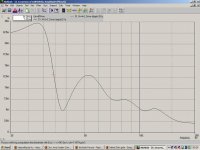
I attach here the Frequency response zipped together with the script in Wordpad.
Best,
Tamas
PS.
Try to model an 1 segment basshorn and a folded one in AkAbak! you will see the difference.
Furthermore I did integrate all the dimensions into one bigger horn in order to get more precise results instead of model 4 systems of one LABhorn!!!
My prediction shows peak Xcursion, not peak to peak! My measurement ( Zip file see earlier post) Shows however Peak to Peak values due to my measurement technique (see Laser geometry)
I attach here the Frequency response zipped together with the script in Wordpad.
Best,
Tamas
PS.
Try to model an 1 segment basshorn and a folded one in AkAbak! you will see the difference.
Furthermore I did integrate all the dimensions into one bigger horn in order to get more precise results instead of model 4 systems of one LABhorn!!!
Attachments
Hello,
My script is totally different than yours. I don`t think our difference in freq. response and excursion all occurs because you intergrated the folds but we also used different volume`s etc..
This is my script;
System 'S6'
Driver 'D1' Def='lab12-1' Node=1=0=20=22
Driver 'D2' Def='lab12-1' Node=1=0=20=22
Driver 'D3' Def='lab12-1' Node=1=0=20=22
Driver 'D4' Def='lab12-1' Node=1=0=20=22
Driver 'D5' Def='lab12-1' Node=1=0=20=22
Driver 'D6' Def='lab12-1' Node=1=0=20=22
Driver 'D7' Def='lab12-1' Node=1=0=20=22
Driver 'D8' Def='lab12-1' Node=1=0=20=22
Enclosure 'E1' Node=22
Vb=172L Sb=0
Waveguide 'Ho10' Node=20=21
STh=2064cm2 SMo=26401cm2
Vf=22.296L Len=3.15m T=0.5
Radiator 'Ho10' Def='Ho10' Node=21
x=0 y=0 z=0 HAngle=0 VAngle=0
When you see my simulated freq. respons (mouth pressure) lay it over the simulations of TD (lsp documentation page (also mouth pressure)) you notice they are identically the same.
Personal i think Labhorns can never be driver with 85V RMS, also when driven in a 4-pack. (85V*85V)/3=2408W!! 1200-1600W would be more realistic, but also than you have the problem of the big peak at 30Hz going way over xmax.
I also read somewhere that TD explained that xmax was reached at 30Hz and pushing out a mouth pressure of 146dB.
The excursion plots in Akabak still remains confusing.
By
Marcel
Hi Marcello,
I wrote my script based on the V1 Labhorn.
My measurements (frequency graph) shows very similar results
(142dB @30Hz, 149 dB@50 Hz) with 80Vrms for a stack of 4 labsubs...
Regarding your model of 4x Beyma 15" Tapped Horn, what are the dimensions of the cabinets? (how big they are?)
Did you model it with the folds or jut as a straight horn?
Did you calculated with the dimensions of the front plate of the stack of the 4 boxes?
Thanks,
Tamas
Hello,
The beyma tapped horns would as small as the TH-115 versions, with a horn path of +/- 250cm. It should be real powerfull. Making an tapped horn in one time from an script is difficult, because you don`t know if the horn you build is presenting the right impedance like you modelled. So i am going to build it step by step; building, measuring, adjusting etc.....
I am not taking into accounts folding`s. Like TD mentioned you need to have the right total horn volume as it would be straight.
When i am simulation a horn i look at the mouth pressure, and not taking into account directivity. After all directivity has a positive influence on the on-axis respons. Subtract 5 a 6 dB for the 1 mtr reference.
A few years ago i bought a book called "Introduction to electroacoustics and audio amplifier design" written by Marshall Leach. I can say this that every penny spending on this book is worth the money. This books explaining the electoacoustics very well and is detailed with a lot of examples (including horns).
How did driven you 4-pack labhorns. Did you put 85V RMS into
1 box? I hope it`s not sine wave. What was you input signal?
Marcel
Marcello,
Is the Leach book still in print? I've been looking for a good book that covers electroacoustics, and if Leach's book goes further into horn theory than his AES paper, it may just be the book I buy.
If Amazon.com has it, even better.
Is the Leach book still in print? I've been looking for a good book that covers electroacoustics, and if Leach's book goes further into horn theory than his AES paper, it may just be the book I buy.
If Amazon.com has it, even better.
Hi,
Thanks for this thread!
I build my first tapped horn today.
I read this thread yesterday and got the hornresp program yesterday.
I have a lot of 12",15" lowQ guitarspeakers and 2*peerless Resolution 10 (for a table tuba projekt)
http://www.tymphany.com/datasheet/printview.php?id=314
I used the peerless and made a calculation for a 40hz horn with a 220cm horn in a 122*26*30 cm box.
I made it ready today and it sounds promising.
n00bishness
Sorry for the n00b post, but in McBean's Hornresp, what causes the Tapped Horn Wizard menu option to become available? I haven't been able to access it at all.
Sorry for the n00b post, but in McBean's Hornresp, what causes the Tapped Horn Wizard menu option to become available? I haven't been able to access it at all.
lokk at the help inside the programm (it´s page 12, if I remember correctly). Only if all parameters are set for a TH, the wizard becomes available.
Well, I've already tried many different combinations of parameters, and no dice. So what combination of parameters is necessary to make the menu option light up? Do I need to not have a front or rear chamber? Right now I've got no rear chamber, but I've got a front chamber for compression.
front and rear chamber must be zero, otherwise you won´t be able to calculate a TH. As soon, as hornresp asks you to "model a tapped horn" when pressing "calculate", you should be able to use the wizard.
I've been building horns for close to fifteen years now, and modeling them on the PC for about five. One thing I've noticed is that a lot of "conventional" subwoofers just DON'T WORK in a horn. A lot of guys try using a twelve or a fifteen in a horn, and find out the hard way that the box becomes huuuuuuuuuge. This is because the surface area of the woofer affects the size of the horn.
So if you want a SMALL horn, you gotta use a SMALL subwoofer.
I love the MCM and Tangband 8" woofers, and I've published three or four designs online that use them. But the requirements for a tapped horn are different, because tapped horns "like" subwoofers that have a higher FS.
So what's the solution?
Car audio subs.
Danley himself appears to be using car subs in his mondo tapped horn, the tapped horn that's the size of a mobile home.
If anyone else is curious to try out car audio drivers in a tapped horn, take a look at this eight:
9Kv.2 Subwoofer
Qts: .30
Qes: .38
Qms: 3.5
Fs: 23 Hz
Re: 7.4
Vas: 45 L
Mms: 71.4 g
Bl: 15.34 T*m
SPL: 83.43 dB
Sd: 231 cm^2
Xmax: 14.1 mm
Voice Coil: 38 mm
Magnet Width: 4.800"
Cutout Diameter: 7.25"
Mounting Depth: 4.375"
Weight: 10 lb
Total Height: 4.900"
Displacement: .05 ft^3
Outside Diameter: 8.375"
http://www.edesignaudio.com/edv2/product_info.php?t=2&products_id=29
I have a discount code I can give you that will let you get the driver for fifty five bucks. I don't want to abuse it, so I'd prefer not to post it online.
Q for William Cowan re the 60Hz TH.
What's the sound quality like? The design looks like it might be a contender for use between a large tapped horn for <60Hz and something like an Azura or Oris at 150-200Hz. I'm also guessing that a # shaped matrix style bracing arrangement (compensating for volume differences) with lots of holes between the chambers would work to make the enclosures stiffer, especially on the larger units.
What's the sound quality like? The design looks like it might be a contender for use between a large tapped horn for <60Hz and something like an Azura or Oris at 150-200Hz. I'm also guessing that a # shaped matrix style bracing arrangement (compensating for volume differences) with lots of holes between the chambers would work to make the enclosures stiffer, especially on the larger units.
- Home
- Loudspeakers
- Subwoofers
- Collaborative Tapped horn project