JinMTVT said:nice info as always ...
i might be quite a bit OT
I have still to understand how you can have a smaller mouth area and still work in the same freq range ...
More good questions! Thank you.
As the mouth size of a horn is reduced, the efficiency becomes lower, and the response becomes more ragged. Ironically, REDUCING the volume of the horn lowers the F3 (but reduces efficency too.)
The front and rear wave are both interacting. That's why coming up with a good response/phase curve is all but impossible without Akabak or Hornresp.Originally posted by JinMTVT and how exactly does a tapped horn work in terms of waves and loading ? what is the front wave of the driver doing ?
Sorry bro, this is a mistake I see a lot of horn newbies make. They ask, what if I built the "optimal" horn?Originally posted by JinMTVT what would be the size of a front loaded horn that would work for 20hz? ( base theorical size )
i do have alot of space avaialble for my HT sub bass unit!
Just for the sake of argument, let's say you build a optimal front loaded horn. It's going to be the size of a volkswagen. Let's say it's 100db efficient. Are you with me so far?
So you have a 100db efficient horn, it's the size of a car, and you feed it 1000 watts. That will give you 130db, right? Nothing to sneeze at.
But wait a minute...
What if you use a TWO tapped horns? It's not difficult to build a tapped horn that's 94db efficient. And you could squeeze two of them into a closet. Now feed each one 1000 watts, and what do you get? That's right, you get 130db. From a box that's 1/8th the size and costs less to build.
Once you start considering the SPACE requirements of a front loaded horn, tapped horns look better & better by the minute.
There's a REASON that Danley Sound Labs doesn't sell ANY front loaded horns, despite inventing one of the best-known ones in the world (the Lab Sub.)
A 20hz sound wave is about as long as a CAR. Yes, a CAR length!
In the rest of the world (i.e. not the US where people drive humongous gaz guzzlers) a 20 Hz wavelength is about the length of 3 to 4 cars !! 😉 😀
Regards
Charles
ok ...
so now we get to the main problem of the horn...
delay
how to cope with the delay ?
do we have to delay everything else to match the horn??
( mid+high + video )??
so now we get to the main problem of the horn...
delay
how to cope with the delay ?
do we have to delay everything else to match the horn??
( mid+high + video )??
is there any upper range(Hz) of a horn operation
hi all
a Small conceptual question about horns
suppose i make a 4 meter long horn, its gonna give me upto 50hz but wats the higher limit
(1/4 wavelength horn of 4 mts). I mean will it work only upto 2-3K hz or upto full range??
More explanation about my question-
i have a big 4 meter horn, can i fix only sub woofers and woofers in it or i can also stick a full range speaker in horn.
The horn will be too big for a 5kHZ signal so will that be an issue ????
A 4M long horn will have an Fc of around 21.5hz if done properly.
It will not likely be useable above 200hz (one decade of response).
A BLH will give about 2 octaves of bass before starting to go, and will act like a direct radiator above there.
RCA made some combination BLH with a front load horn with a special 8" speaker that were useable from about 50hz to 7Khz~10Khz. The transition occurred about 200hz (two octaves above cut-off) and created a dip at the transition frequency (a similar dip exists in a straight BLH where it transitions to a direct radiator).
djk said:A 4M long horn will have an Fc of around 21.5hz if done properly.
It will not likely be useable above 200hz (one decade of response).
thanks a lot DJK
1 octave....will remember this
by the way what you said is true only for tapped horn or for any horn like for example synergy horns...
1 more tiny thing, horn is diffrent for diffrent speaker, is it...
sorry for such a silly question
One decade is a little over three octaves (20hz~200hz).
That applies to most straight front-loaded horns.
The tapped horn (in singles) is more like two octaves (similar to a BLH).
While there are straight front-loaded horns designed for 300hz~16Khz, they don't sound the best in either the bottom or top octave (so they are not much over a decade at 600hz~8Khz).
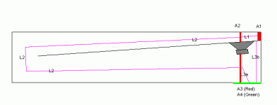
Names, terms, definitions..
Hullo,
I'm trying to sim these B139's I have in some TH, but I'm sort of stuck, because I just can't seem to find the right values.
In the 'generic' TH AKABAK script provides here, there are 4 areas, and 3 lengths.
I Tried to sim a 180cm long Cowan-style box, inside width (ex-baffle) 37.5cm, height 30cm.
Say the center of the driver is 15cm 'into' the horn (Or maybe 25: I might put 2 in there like this --^^-| where the 25cm is right in between the two ^^'s...
Baffle starts at 10cm off the back, ends 18,5 off the back and 20 from the side.
A can seem to figure a0: Surface at extreme start of horn: 10cm*30cm=300
But then, L1: the length to the back of the driver... that is: The length following the centerline of the horn, until I reach a line perpendicular to the center of the driver?
and the same for L2 ?
and L3? followin the centerline as well?
And a4 is the SURFACE of the big hole gaping in the front, right?
I've put this in a little picture: Maybe someone can help me (us?) setting up the proper definitions?
Regards, Paul
(Looking to make some sawdust... ;-) )
Attachments
I have two Adire Audio Koda 8 . I've modelled a single and got a box with a very acceptably sized footprint that nearly reaches the ceiling 😉 Not particularly sensitive at 94dB/1W but the -3dB point is 22Hz . How do you model two drivers ? Is it a case of doubling some of the TS parameters or is a whole new script required ? I'm up to page 4 of the Akabak manual and could do with a little help 🙂
cheers
316a
cheers
316a
Re: Names, terms, definitions..
Yes sawdust , I've been waiting all summer for the rain to stop 😉
The B139 may not be suitable for a tapped horn . I'm pretty sure this is only rated for 25 watts and has limited xmax . Do you have the TS parameters , I'll have a crack at a horn for you 🙂
cheers
316a
bibster said:Hullo,
I'm trying to sim these B139's I have in some TH, but I'm sort of stuck, because I just can't seem to find the right values.
(Looking to make some sawdust... ;-) )
Yes sawdust , I've been waiting all summer for the rain to stop 😉
The B139 may not be suitable for a tapped horn . I'm pretty sure this is only rated for 25 watts and has limited xmax . Do you have the TS parameters , I'll have a crack at a horn for you 🙂
cheers
316a
Re: Re: Names, terms, definitions..
Kef B139 rough model , driver seems to model best moved up the line
cheers
316a
Kef B139 rough model , driver seems to model best moved up the line
| Kef Tapped Horn
Def_Const |Horn Dimensions
{
a1 = 100e-4; |Area at throat (cm^2)
a2 = 102e-4; |Area at rear of driver (cm^2)
a3 = 580e-4; |Area at front of driver (cm^2)
a4 = 585e-4; |Area at mouth (cm^2)
l1 = 45e-2; |Distance from throat to rear of driver (cm)
l2 = 410e-2; |Line distance from rear of driver to front of driver (cm)
l3 = 45e-2; |Distance from front of driver to mouth (cm)
}
Def_Driver 'Dr1'
| Kef B139
Sd=338.2cm2
fs=22.8Hz
Qes=0.41
Qms=0.3793
Vas=98.7L
Re=7.6ohm
system 'S1'
Driver Def='Dr1' Node=1=0=3=4
Waveguide 'W1' Node=2=3 STh={a1} SMo={a2} Len={l1} Conical
Waveguide 'W2' Node=3=4 STh={a2} SMo={a3} Len={l2} Conical
Horn 'H1' Node=4 STh={a3} SMo={a4} Len={l3} Conical
cheers
316a
Hi 316a !
Thanks for yer efford! But alas, a bit too late, as I did fetch some MDF the other day, and made a copy of Cowen's 30Hz horn.
Played a bit with AkAbak, and was quite please with the B139 at 12cm of the start of the horn, so that's what I build... (I can always replace the driver with a suitable 12" )
See here:
http://chanac.zapto.org/TH/
(Hope it works, can't test from here, and mice keep turning my NAS off. And the 'site' being on the NAS.... you get it)
Not yet ready to measure (Need to glue'n'fix the lid, seal the driver, connect it properly, but mainly lack of proper mic....)
Cheers, Paul
PS: Still don't know how to interpret the dimensions, especially L3, and A3 & A4
Paul
Re: Re: Names, terms, definitions..
100W Program, and 7mm Xmax (+/- 3.5 thus)
Enough for some testing and fun, right....
Cheers, Paul
Dave (Planet10) says on his site: http://homepage.mac.com/planet10/TLS/drivers/images/B139B_newer.gif316a said:I'm pretty sure this is only rated for 25 watts and has limited xmax .
100W Program, and 7mm Xmax (+/- 3.5 thus)
Enough for some testing and fun, right....
Cheers, Paul
Yello!
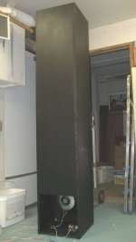
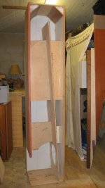
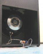
I have finnished my prototype tapped horn and I was surprised that it really works. I built it from scrap pieces from old projects and the driver, Precision Devices 12SB30 was really cheap. This project is a steal.
The horn is 25Hz (3,44m) version, WxHxD dimensions are 366x1914x388 (mm). I ran some test tones in the garage and everything was resonating during sweep from 10Hz - 100Hz (driver cone barely moved at all). My XO is ancient 120Hz low-pass 12dB I think. But more listening impressions when I get it to my AV-reciever with proper XO's and some hollywood effects.
I have played with different subwoofer builds for many years and at last I can say that this thing is scaring the jeepers out of me...
and here's some "eye candy"
Attachments
Tuomas,
Very cool. How did you determine that line taper? It seems pretty radical. Is the line length based on 1/2 lambda of the driver Fs, or does the driver Fs have nothing to do with it, i.e. the line length is 1/2 lambda at 25 Hz.?
Very cool. How did you determine that line taper? It seems pretty radical. Is the line length based on 1/2 lambda of the driver Fs, or does the driver Fs have nothing to do with it, i.e. the line length is 1/2 lambda at 25 Hz.?
Bob,
erm, yes...
Driver Fs = 50Hz -> line lenght with 1/2 lambda from Fs is 3.44m
or 344m/25Hz and quater-wave from that is 3.44m line length.
Mouth was set to driver Sd but I ended up with almost 2x Sd
Throat is 1/4 Sd. (I had no idea how to set throat or mouth, it's just a prototype) 😉
So far so good. Sub plays well in the garage. The garage fits one small european car or half of dodge ram or so. It's a small place and I think that this sub is way oversized for this space. Listening to organ music is scary.
--
Tuomas
Just for curiosity, what are differences between quater-wave horn and half-wave horn, in terms of phase and delay?
--
Tuomas
--
Tuomas
cowanaudio said:G'day Paul
>Another idea - what if a second driver was used and placed higher up - it would be like a second tapped horn tuned higher.
>William did you try anything like this and do you think it could prove an answer?
We tried this with two drivers in the 30 Hz horn, and it didn't help. Here's a picture of one of the spaced driver test boxes, in the other the top driver was 1/2 way up the line. I'll have to look for the plots. They were nothing special.
Cheers
William Cowan
http://www.diyaudio.com/forums/attachment.php?s=&postid=1163742&action=thumb&stamp=1174451056
Looking for more bandwidth I was thinking along the lines of two close spaced woofer drivers as Bill did here in this picture on the left cabinet, but with the output opening extended up the line to behind the upper woofer as a Karlson type slot rather than truncated abruptly at the beginning of the long path driver as shown. Has anyone tried this idea?
- Home
- Loudspeakers
- Subwoofers
- Collaborative Tapped horn project