your projects are always so brilliantly nuts... 😀
Nuts? Here's "nuts" 🙂
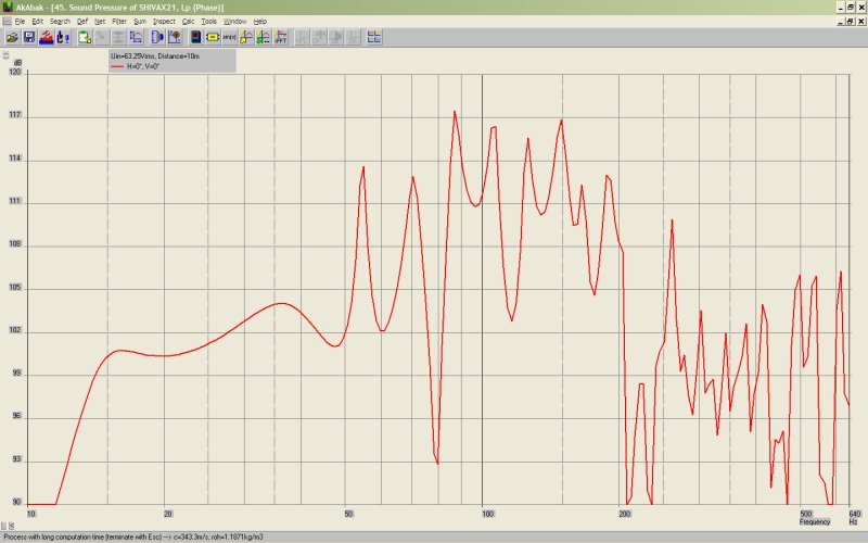
This is a tapped horn with three subwoofers on the same line. The "high frequency" subs are MCM 55-2421. About $60. Filling in the sub-bass is an Exodus Audio Shiva X2. Basically we tune the tapped horn with a line that's somewhere between ideal for both woofers. The cool thing about this box is that it spreads out the resonances, and that prevents any humongous peaks and dips. Sure, there are some small ones, but nothing that will be particularly audible.
An externally hosted image should be here but it was not working when we last tested it.
An externally hosted image should be here but it was not working when we last tested it.
Here's some pics of our woofers. Exodus Audio Shiva X2 at the top, MCM 55-2421 at the bottom. About $300 for both.
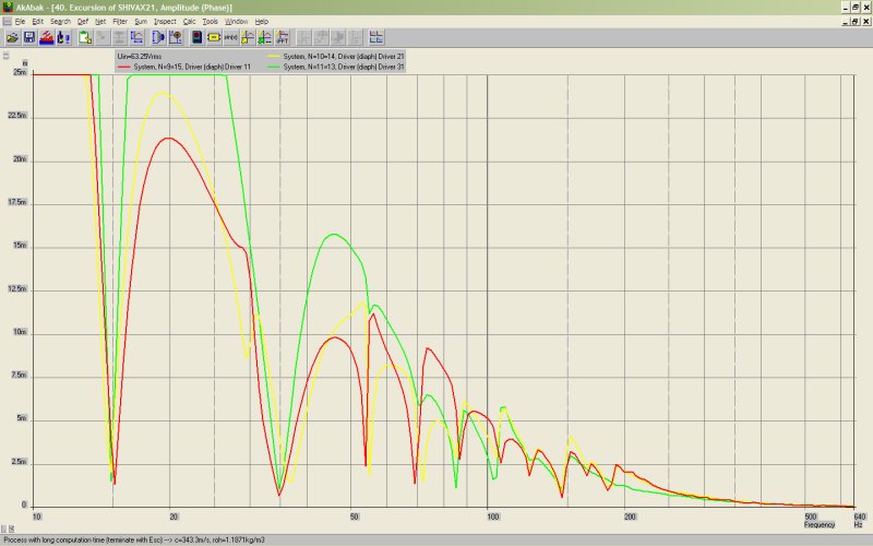
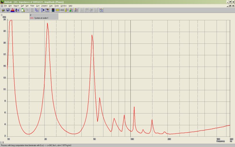
Here's the excursion and the impedance of the subwoofer. Note that the box is designed to stagger the impedance peaks, and also smooth out the excursion dips. Basically, if a big fat bass note hits, all three woofers won't bottom out. The dips are staggered. The end result is flat response, in the two octaves from 12.5hz to 50hz.(+/- 3dB) And usable response to 200hz, assuming that those peaks and dips will be smoother "in real life."
Here's the Akabak model.
|================================================= ================================================== =====
|REQUIRED AKABAK SETTINGS:
|File > Preferences > Physical system constants:
|Sound velocity c = 344m/s
|Medium density rho = 1.205kg/m3
|Sum > Acoustic power:
|Frequency range = 10Hz to 20kHz
|Points = 533
|Input voltage = 31.62V rms
|Integration = 2Pi-sr
|Integration steps = 1 degree ... 1 degree
|Integration method = Cross
|================================================= ================================================== =====
Def_Const |Hornresp Input Parameter Values
{
|Length, area and volume values converted to metres, square metres and cubic metres:
Rg = 0.01e-0; |Amplifier output resistance (ohms)
S1 = 75.000e-4; |Horn segment 1 throat area (sq cm)
S2 = 100.00e-4; |Horn segment 1 mouth area and horn segment 2 throat area (sq cm)
S3 = 190.00e-4; |Horn segment 2 mouth area and horn segment 3 throat area (sq cm)
S4 = 375.00e-4; |Horn segment 3 mouth area and horn segment 4 throat area (sq cm)
S5 = 750.00e-4; |Horn segment 4 mouth area and horn segment 5 throat area (sq cm)
S6 = 1050.00e-4; |Horn segment 5 mouth area and horn segment 6 throat area (sq cm)
S7 = 1200.00e-4; |Horn segment 5 mouth area and horn segment 6 throat area (sq cm)
S8 = 1400.00e-4; |Horn segment 5 mouth area and horn segment 6 throat area (sq cm)
S9 = 2700.00e-4; |Horn segment 6 mouth area (sq cm)
L12 = 100.00e-2; |Horn segment 1 axial length (cm)
L23 = 25.40e-2; |Horn segment 2 axial length (cm)
L34 = 40.64e-2; |Horn segment 3 axial length (cm)
L45 = 360.00e-2; |Horn segment 4 axial length (cm)
L56 = 180.00e-2; |Horn segment 5 axial length (cm)
L67 = 40.64e-2; |Horn segment 6 axial length (cm)
L78 = 25.40e-2; |Horn segment 6 axial length (cm)
L89 = 102.00e-2; |Horn segment 6 axial length (cm)
|Parameter Conversions:
Sd = 946.00e-4; |Total diaphragm area for 3 parallel drivers (sq cm)
}
Def_Driver '55-2421'
Sd=220.00cm2
Bl=14.56Tm
Cms=3.48E-04m/N
Rms=1.20Ns/m
fs=31.00Hz |Mmd = 73.86g not recognised by AkAbak, fs calculated and used instead
Le=2.42mH
Re=3.40ohm
ExpoLe=1
Def_Driver 'Shiva X2'
Sd=506.00cm2
Bl=15.4Tm
Cms=2.66E-04m/N
Rms=9.09Ns/m
fs=21.30Hz |Mmd = 73.86g not recognised by AkAbak, fs calculated and used instead
Le=0.95mH
Re=3.80ohm
ExpoLe=1
System 'System'
Resistor 'Amplifier Rg'
Node=1=2
R={Rg}
Driver Def='55-2421''Driver 11'
Node=2=17=9=15
Driver Def='55-2421''Driver 21'
Node=17=0=10=14
Driver Def='Shiva X2''Driver 31'
Node=2=0=11=13
Waveguide 'Horn segment 1'
Node=8=9
STh={S1}
SMo={S2}
Len={L12}
Conical
Waveguide 'Horn segment 2'
Node=9=10
STh={S2}
SMo={S3}
Len={L23}
Conical
Waveguide 'Horn segment 3'
Node=10=11
STh={S3}
SMo={S4}
Len={L34}
Conical
Waveguide 'Horn segment 4'
Node=11=12
STh={S4}
SMo={S5}
Len={L45}
Conical
Waveguide 'Horn segment 5'
Node=12=13
STh={S5}
SMo={S6}
Len={L56}
Conical
Waveguide 'Horn segment 6'
Node=13=14
STh={S6}
SMo={S7}
Len={L67}
Conical
Waveguide 'Horn segment 7'
Node=14=15
STh={S7}
SMo={S8}
Len={L78}
Conical
Waveguide 'Horn segment 8'
Node=15=16
STh={S8}
SMo={S9}
Len={L89}
Conical
Radiator 'Horn mouth'
Node=16
SD={S9}
Patrick,
Regarding the frequency response of your midbass project, have you considered the following points?
- You haven't included the filters in the design, therefore the HF response may not be correct.
- Akabak response predictions can be inaccurate when the area dimensions exceed about half a wavelength at the frequencies of interest.
- I have some reservations about the excursion limiting effects that you claim. I agree that sizing the line to interleave the impedance curves is a good idea. Horst Moller does a similar thing in his "Doppelhorn" designs. In his case, he uses two separate different length horns. His aim is to reduce the impedance variations presented to the amplifier. I tried modelling a pair of such horns with a common mouth, but found that they had to have a very restrictive mouth (mutual coupling) to provide significant excursion reduction. I couldn't see how to practically couple the throat end as well as the mouth, but your idea of using different parameter drivers will do it. I'll have a look at your excellent Akabak script.
Anyway, I applaud your efforts. The deliberate use of different drivers to cover an overlapping frequency range is something that was done in an empirical fashion many years ago. I'm not aware of anyone having applied some scientific rigour to its analysis. Either it has been tried and it doesn't work so was not reported, or it simply hasn't been done until now.
I wondered about the series wiring of the two 8 inch drivers in your bass horn design. Series connection when the enclosure or driver parameters differ is usually a bad idea. If you plot the excursion curves, you will see that the 8 inch drivers perform a merry dance with relation to each other. For simulation purposes, you might wish to try wiring them in parallel and driving them from a half voltage source. I usually use an opamp to implement this:
Resistor 'Divider Top'
Node=1=111
R=10kohm
Resistor 'Divider Bottom'
Node=111=0
R=10kohm
OpAmp 'Op1' Node=111=17=17 Rg={Rg}
Driver Def='55-2421' 'Driver 11'
Node=17=0=9=15
Driver Def='55-2421' 'Driver 21'
Node=17=0=10=14
You should see a very similar overall response curve, but lower overall excursion for the 8 inch drivers.
Patrick,
Regarding the frequency response of your midbass project, have you considered the following points?
- You haven't included the filters in the design, therefore the HF response may not be correct.
- Akabak response predictions can be inaccurate when the area dimensions exceed about half a wavelength at the frequencies of interest.
The use of multiple woofers seems to smooth things out pretty nicely.
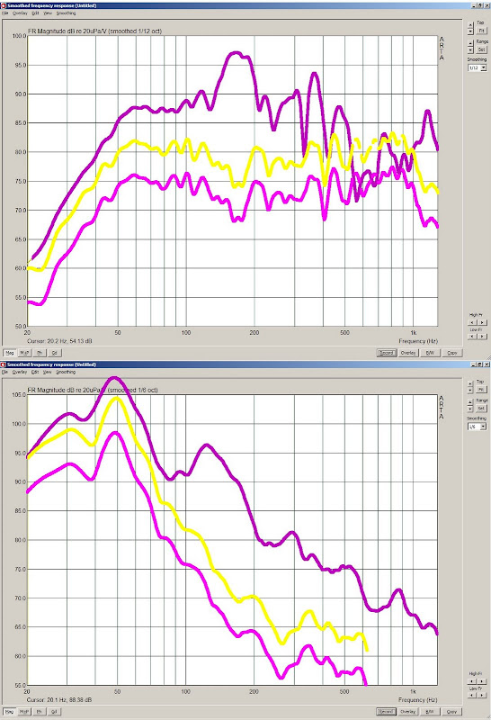
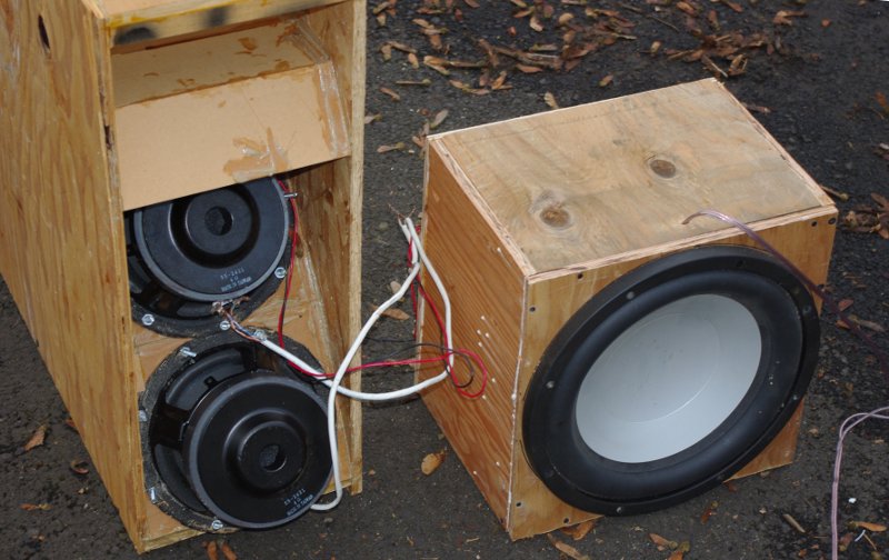
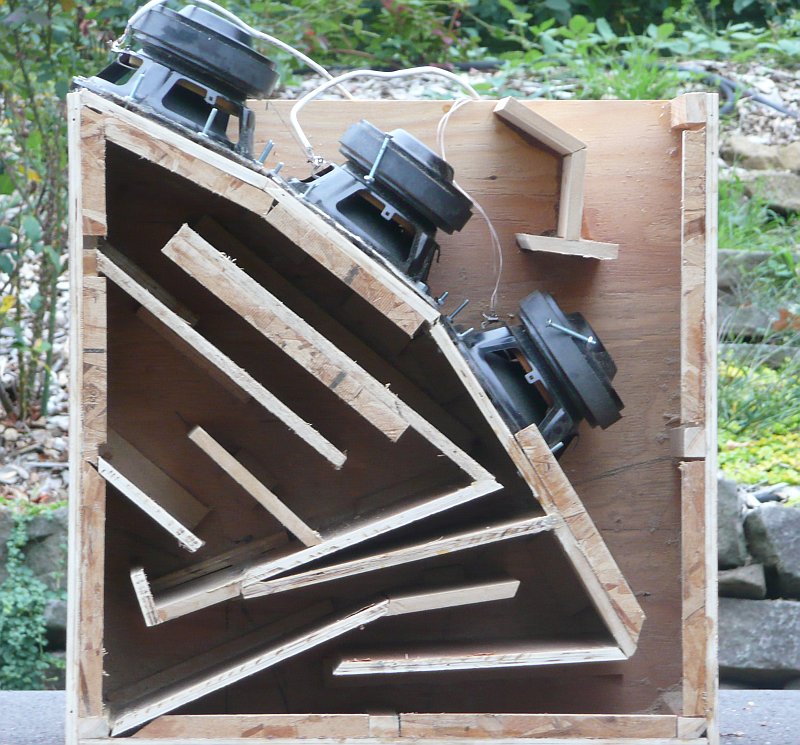
Here's some photos, and a measurement, of a triple driver tapped horn. In the graph, the TH is the one with the most SPL.
While working on a midrange horn, it occurred to me that there's no real reason you can't mix drivers in a tapped horn. For instance, I have some twelves here that would require an insanely large horn to achieve smooth response. But I also have some eights that would work nicely, but won't play as low as the twelves. Solution: use two eights *and* a twelve.
- I have some reservations about the excursion limiting effects that you claim. I agree that sizing the line to interleave the impedance curves is a good idea. Horst Moller does a similar thing in his "Doppelhorn" designs. In his case, he uses two separate different length horns. His aim is to reduce the impedance variations presented to the amplifier. I tried modelling a pair of such horns with a common mouth, but found that they had to have a very restrictive mouth (mutual coupling) to provide significant excursion reduction. I couldn't see how to practically couple the throat end as well as the mouth, but your idea of using different parameter drivers will do it. I'll have a look at your excellent Akabak script.
Anyway, I applaud your efforts. The deliberate use of different drivers to cover an overlapping frequency range is something that was done in an empirical fashion many years ago. I'm not aware of anyone having applied some scientific rigour to its analysis. Either it has been tried and it doesn't work so was not reported, or it simply hasn't been done until now.
hmm, you could go even further with this, put both woofers on different amps and use time alignment for different response. or am i saying something really stupid there ?
Last edited:
Aren't they thoughyou projects are always so brilliantly nuts... 😀

Hi.
I've only read to page 70 so far, but i have a question i doubt have been answered.
If i want to make a tapped horn, where the first 150cm is constant (not a horn), and the following 170cm is conical. Why does the frequency response in hornresp look like the path of the sound is only 170cm?
I've only read to page 70 so far, but i have a question i doubt have been answered.
If i want to make a tapped horn, where the first 150cm is constant (not a horn), and the following 170cm is conical. Why does the frequency response in hornresp look like the path of the sound is only 170cm?
I have to make the constant part ridiculously long to make any difference at all, but it does not seem like i loose any efficiency worth mentioning, smaller peaks, but that's about it.
Basically, you are describing a TH with a compression throat chamber. Try using Ap1 as your constant cross section area. Lpt = 150cm. Vtc = speaker mounting plate thickness...1/2", 5/8", or 3/4". Apt = Sd or speaker cutout diameter.Hi.
I've only read to page 70 so far, but i have a question i doubt have been answered.
If i want to make a tapped horn, where the first 150cm is constant (not a horn), and the following 170cm is conical. Why does the frequency response in hornresp look like the path of the sound is only 170cm?
Is there a consensus for this thread on which design(s) are recommended for the masses? Can someone reply with the post/page numbers (or even links into this thread)? It would be great if the OP could edit the first post to list these.
Thanks,
Darrell
Thanks,
Darrell
Tang Band W6-1139SI TH designs
Hi, I'm looking for Tang Band W6-1139SI TH design plans,
I've read through the volvotreter 30 and 38Hz designs, and also
Tapped Horn Subwoofer - amateur audio
and the designer told me that these are one of the first DIY TH efforts which are a little outdated by now.
Is that the case? are there better/updated designs out there for the W6?
Please point me in the right direction
Best regards
Why don't you get Hornresp and Sketchup and a woofer tester and design your own? I would cost less and give better results than following someone else's design because you can give it your design priorities. That's the spirit of DIY after all. If you don't think you have that ability tell me what you're looking for and I'll design it for you.
I had a read on hornresp and arabak and I can see where things are going, but then i look at the folding, maybe a single or double fold I can just about see, but any more fancy than that its like doing integrals in uni all over again, and I'll need to buy a woofer tester.
But you have convinced me. It didnt take much did it!? I want to build a front loaded horn by BFM and a similar sized/priced tapped horn that is properly designed and see for myself what the differences are. I'm going to order a WT3 next week and get things started. But if I cant get the simulation working, you would really help me design it?
right now I have these candidates:
W6-1139SI 6-1/2"
Tang Band W6-1139SI 6-1/2" Subwoofer | Parts-Express.com
Audax HT240 10"
* Power handling: 160 watts RMS/225 watts max
* VCdia: 1.5"
* Le: 0.67 mH
* Impedance: 4 ohms
* Re: 2.9 ohms
* Frequency range: 49-1,150 Hz
* Magnet weight: 63 oz.
* Fs: 48.9 Hz
* SPL: 92 dB 2.83V/1m
* Vas: 1.27 cu. ft.
* Qms: 10.01
* Qes: 0.72
* Qts: 0.67
* Xmax: 7 mm
* Dimensions: Overall Diameter: 9-3/4", Cutout Diameter: 8-11/16", Mounting Depth: 4".
DIYMA 12"
* QTS: .354
* FS: 25hz
* VAS: 41.7 L
* RE: 3.6 Ohm
* BL: 22
* SPL: 84.3 dbwm
* Le: 1.3mh
* Xmax: 23mm 1 way (71% bl, 25% cms)
* Xmech: 64mm peak to peak
* Weight: 37 lbs
* Cutout diameter: 28cm
* Mounting depth: 16cm
* Driver volume: .15 cft
ACI SV10
https://www.madisound.com/store/manuals/SV10Specs.pdf
RSDC102
Re (Dcr ohms) 0.85 (in parallel)
Fo (Hz) 27.9
Sd (SqM) 0.0314
BL (Tm) 7.57
SPL (dB@2.83V) 92.6
Qms 4.04
Qes 0.461
Qts 0.414
Vas (liters) 27.8
Cms (um/N) 183.9
Mms (gms) 177.5
Power Handling (RMS) 600W
Xmax (mm) 14.8
VC (in) 2.5˝
I was thinking of just finding a good design for the W6, because I dont know how to model any of the others to compare.
I guess I would be shooting for a bandwidth around 20-100Hz, maybe just 30-80, depending on the efficiency and size. Efficiency is VERY important for me, I was told a bass horn should be at least 6db more efficient than a vented box, otherwise the extra complexity and space is not worth while.
what do u think?
Last edited:
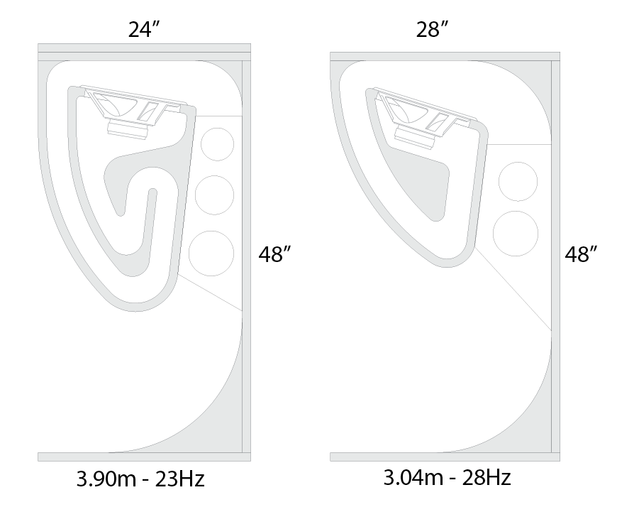
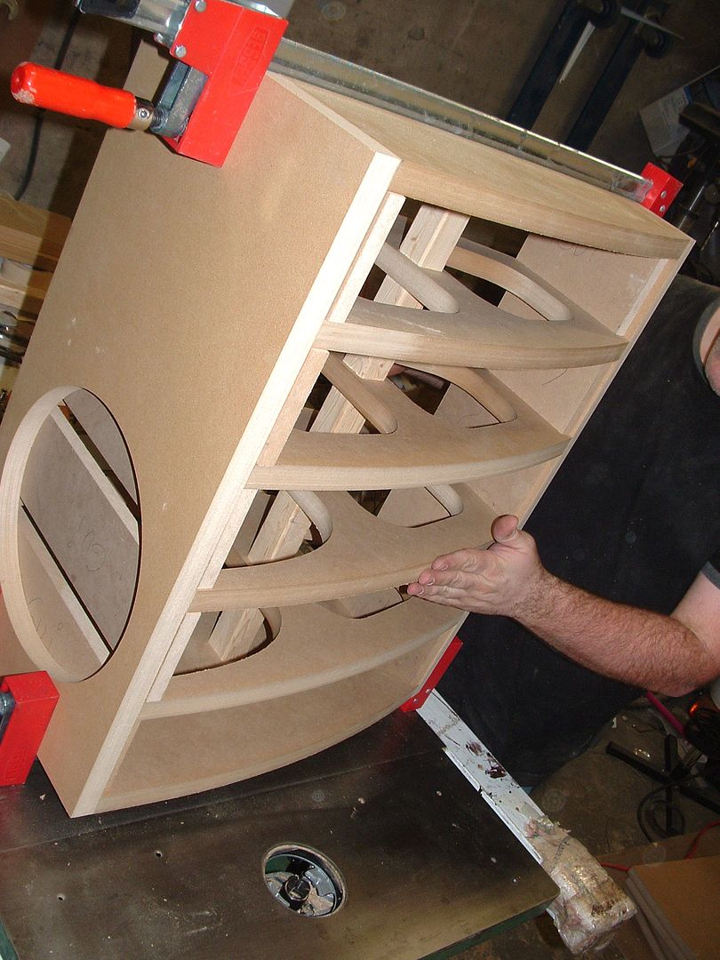
Hi all. Please allow me to add my current project to the many experimentations on this thread. First off, I am a huge early Kef enthusiast, so the horn cabinets had to be made with a Kef driver. I have four Kef B300 with 23Hz Fs for the purpose (on top of the other 4 already in duty). The cabinets are for home, and therefore all out SPL is not the goal. I am looking for low frequency. And "relatively" small cabinets. I looked at Cerwin-Vega's bass bins and extrapolated on their design (folded horn) but added a few spices: no sealed enclosure for the driver but a simple open labyrinth. The woomb-like portion is made fron CNC-cut layers of 1" MDF glued, stacked and compressed. Allowing to get any shape. Section is 2.5" x 14" (might enlarge to 3")
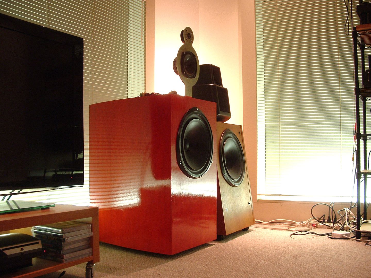
One previous project. Still developping the "heads". Speakers are tri-amped.
An externally hosted image should be here but it was not working when we last tested it.
One previous project. Still developping the "heads". Speakers are tri-amped.
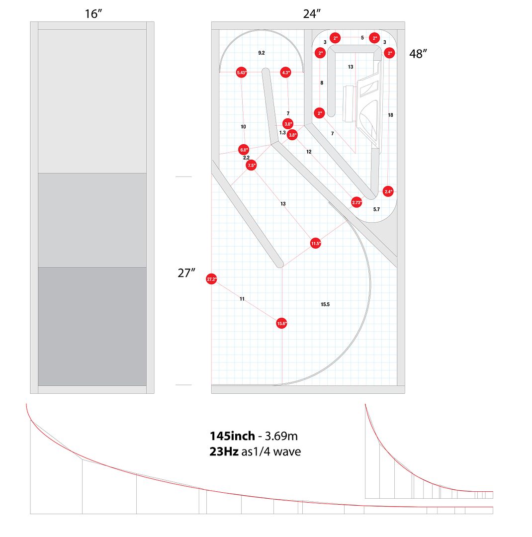
In order to lower the production costs, I have redesigned the enclosure. Feel free to use at you own risks. Enclosure meant for home use with a 12" driver w/ 23Hz Fs. 1" MDF is used and drawing doesn't show the bracings. The light blue grid reflects a 1"/square.
An externally hosted image should be here but it was not working when we last tested it.
Last edited:
What did you model this enclosure with?
Mark
Ah, ah. I am old school. I fabricate, I listen and measure with pink noise and tone generator. I will submit a graph of the progression of the horn (distance vs height). But if anyone wants to model it, then the specs of the driver are here. 😀
An externally hosted image should be here but it was not working when we last tested it.
- Home
- Loudspeakers
- Subwoofers
- Collaborative Tapped horn project