Photos?
The rest are here http://screamersusa.com/TAPPED.html
Enough holes in the Path15 Box? It's only been rebuilt 11 times in as many days!!!!!!!!!!!!!!
The rest are here http://screamersusa.com/TAPPED.html
An externally hosted image should be here but it was not working when we last tested it.
Enough holes in the Path15 Box? It's only been rebuilt 11 times in as many days!!!!!!!!!!!!!!
I'm planning on building a sub in my garage and firing it into the adjacent living room where my home theater resides. Anyways, I have this old EV 18" sub in enclosure that I can't seem to sell, so I thought I'd model the driver in a TH. I think it looks pretty darn good, almost perfectly flat from 20-60 + 4 at 70 with a peak at 75. Assuming the excursion modeling is accurate it tops out around 46 volts or so, about 265watts. 120db+. (edit: correction, 36volts 165 watts) It would be big...
How does the model look, any mistakes?
| 20 Hz Tapped Horn http://www.eviaudio.co.jp/download/ev/dl18w.pdf
Def_Const |Horn Dimensions
{
a1 = 900e-4; |Area at throat (cm^2)
a2 = 980e-4; |Area at rear of driver (cm^2)
a3 = 2500e-4; |Area at front of driver (cm^2)
a4 = 2501e-4; |Area at mouth (cm^2)
l1 = 25e-2; |Distance from throat to rear of driver (cm)
l2 = 460e-2; |Line distance from rear of driver to front of driver (cm)
l3 = 75e-2; |Distance from front of driver to mouth (cm)
}
Def_Driver 'Dr1'
| EV DL18W
Sd=1300cm2
fs=26Hz
Qes=0.31
Qms=7.32
Vas=553L
Re=6ohm
Le=2.7mH
system 'S1'
Driver Def='Dr1' Node=1=0=3=4
Waveguide 'W1' Node=2=3 STh={a1} SMo={a2} Len={l1} Conical
Waveguide 'W2' Node=3=4 STh={a2} SMo={a3} Len={l2} Conical
Horn 'H1' Node=4 STh={a3} SMo={a4} Len={l3} Conical
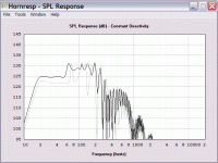
Here's a response plot, 2.83v, 2pi.
Don't know if I'll build it, if I do I might tune a bit higher to move the peak up. Currently my mains play fine to 60, but the plan is to custom build in wall and I'll probably shoot for 80hz.

Don't know if I'll build it, if I do I might tune a bit higher to move the peak up. Currently my mains play fine to 60, but the plan is to custom build in wall and I'll probably shoot for 80hz.

FWIW, using my default calc yields considerably more gain BW, though of course it's almost twice as large as yours at ~1758 L, so no 'free lunch'. Sim assumes a 32 V input for yours (in shadow) and 33 V in mine to reach ~Xmax in the ~22-23 Hz dip:
GM
GM
Attachments
I really need to play around with hornresp. Bigger isn't a problem. I've had this computer rack filled with servers in the garage for years and it's going away. That spot is where the sub is going. I have a 2foot by 3 foot footprint to play with. The roof is 12 feet. That yields just over 2000 liters.
I have a SVS PB12/2 in the corner right where I'd cut a hole in the wall for the horn mouth. I just did a test with a 20 hz sine wave. Unfortunately all I have for measurement is a rat shack meter. I think it's supposed to be 20db down at 20hz. I stopped turning it up when the meter read 100db (maybe 120db actual at listening position) for fear of breaking a window or causing my plaster ceiling to drop. Drivers didn't appear to be close to xmax. Lots of rattles but almost completely from the antique double hung windows. I had ear protection on and I'm still getting a headache. Wonder what the neighbors think?
If I build it I'll build it as efficient as possible, but it'll never be driven to xmax.
One reason I really like this design is the single exit. Makes a nice clean relatively compact hole.
Realistically I'll probably choose a smaller driver with a larger xmax and get the same result or better with 1/4-1/2 the volume, although at the expense of more input power.
I wonder how much gain I could realistically expect? I could place the mouth at floor level with one edge up against the corner.
serenechaos said:Is this with 1/8 space loading?
And what actual amplifier output impedance?
My graph was 2pi. 1/2 space right? As for impedance, are you talking about the modeled network impedance? If so it drops to 6 ohms at the lowest with peaks at 11hz 24hz and 64hz. If I build it I'll drive it with a 400w@8ohm amp that is perfectly happy all the way down to 2ohm when bridged.
serenechaos said:Is this with 1/8 space loading?
And what actual amplifier output impedance?
If you're asking me, I used 1 pi loading for both sims since it's best to put the mouth at floor level away from the corners.......
I always assume a 1/10 ohm minimum of wiring/whatever loss.
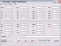
Specs for the sim I did:
Attachments
etcetera said:
My graph was 2pi. 1/2 space right?
Right, if corner loaded, input 0.5 pi. Note that this assumes an infinitely large, rigid room, so there will be losses increasing with decreasing frequency in a typical room.
GM
GM, thanks for posting the specs for your sim, that's was a very fast way for me to understand hornresp.
Originally posted by GM it's best to put the mouth at floor level away from the corners.......
Hello GM, is it a bad thing to put a pair of tapped horns in the corners? What if they also look good enouh when I switch to the 1pi setting?
etcetera said:GM, thanks for posting the specs for your sim, that's was a very fast way for me to understand hornresp.
You're welcome! Didn't realize it was such a good tutorial!
AllenB said:
Hello GM, is it a bad thing to put a pair of tapped horns in the corners? What if they also look good enouh when I switch to the 1pi setting?
Greets!
If by 'corners' you mean on the same wall, then it's certainly not the best positions for dual subs, though my remark was limited to a single sub along the screen wall. A ~ in-depth look at multiple sub positions: http://www.harman.com/wp/pdf/multsubs.pdf
GM
Been looking all over the web for more information on my driver in hopes of being able to build a TH. Hope you guys will give me a hand.
I have 2 of these on the way and I think I am missing only one parameter.. the Sd. I will be able to measure that soon.
Eosone 12 Inch Subwoofer
Designed for a 1.75 - 2.5 ft3 Vented cabinet tuned to 30HZ
Power handeling 125W RMS / 250W Peak
* Impedence 4 ohms
* Power is 250 watts RMS (400 watts Peak)
* 2 inch voice coil
* SPL is 91db at 1 watt at one meter
* Freq. Response 20 Hz. to 1500 Hz.
* Part Number on the woofer is 1RD0001-2
* FS - 23.8926 Hz.
* Revc - 3.2038
* Zmax - 21.2296 ohms
* Qes - 0.5382
* Qms - 3.0342
* Qts - 0.4571
* Le - 2.0306 mH (at 1 kHz)
* Vas - 176.2302 L
Originally used in the Eosone RSP-912 powered subwoofer system
So, got these on ApexJr.
Is it possible to run the simulation from this information or is the Sd absolutely necessary?
I tried Akabak. Will not run on my 64bit computer. I will try to figure out Hornresp.
Thanks for your help,
Uriah
Sd is the surface area of the diaphragm (not including surround). It's probably in the neighborhood of 300-350 square cm, so just use 325 until you can make a proper measurement. It'll be close enough to begin modeling.
Using Sd of 325 gives the following:
Cms 0.0011746 m/N
mms 37.4 g
BL 5.8 Tm
Eric
Using Sd of 325 gives the following:
Cms 0.0011746 m/N
mms 37.4 g
BL 5.8 Tm
Eric
All you had to do was search this forum: http://www.diyaudio.com/forums/showthread.php?postid=1607070#post1607070
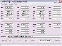
Since there was no interest, I didn't bother to post the design, but here it is so you can input it and play with the Wizard if it's too big/whatever:
GM
Since there was no interest, I didn't bother to post the design, but here it is so you can input it and play with the Wizard if it's too big/whatever:
GM
Attachments
Hi GM.
In fact, I have read that thread and have been in email contact with Nickthevoice. I am here asking questions because neither Nick nor I have all the specs of this driver and neither of us know exactly what the box should be built like.
He built his almost the same as one of the boxes on Mr Cowans site and popped his driver in. To him it sounds great. Shakes the house apart! 🙂
I wanted to get more specific in the design and try to get it spot on if possible.
Thanks for the image. I will try to get that into Hornresp.
Uriah
edit: Record 253 of 790!! Man you have been busy!!
Greets!
Considering the sims I did, it makes me wonder how accurate the specs are. Then again, the room dominates, so it could be a decent match if the room's nulls line up with its simmed peaks.
GM
Considering the sims I did, it makes me wonder how accurate the specs are. Then again, the room dominates, so it could be a decent match if the room's nulls line up with its simmed peaks.
GM
GM or anyone else,
I am frankly completely confused by this program. Would anyone be willing to work with me either here in the forum or by email to figure this driver out for a TH enclosure under 6'5"? I dont mind folding it and I think thats probably a necessity.
Hope someone will help. The program is just over my head and maybe its easy to use but I dont understand the parameters it is asking for. I did input the same numbers on GM's results, but the program has changed since then and one now "CON" is no longer used twice there is now an "L34" instead that will not allow me to populate it but the program is complaining that there is no value for it.
I got far enough that the program allowed me to select "tapped horn" and then it ... well lets just suffice it to say that I am sufficiently confused and hoping for some more help. (right now it thinks S2 is 71,287 square centemeters)
Thanks
Uriah
- Home
- Loudspeakers
- Subwoofers
- Collaborative Tapped horn project


 Eric, thanks a bunch. Maybe I will be able to get this thing figured out tonight.