THe ones you get from cheap sellers are often magnetic wire with the slippery tight covers like you describe..Are those Mueller clips soldered? I've been looking for decent clipleads, too. Ones that are soldered (or that I can solder, as some are clamped in a way that soldering well can't be done). And that don't have such tight and slippery sleeves that I can't squeeze them open wide enough without them squish out of my fingers. I've bought some on the 'bay, at higher than typical cost, that claimed to be soldered. Only to find them only clamped - and badly at that. I have a bag of clipleads but only a few (that I marked) that are trustworthy. I'm open to recommendations
Elenco banana plugs are definitely a step above, not sure if their clip leads are better than the cheap ones or not. I bought a set but I don't have it handy to check..
Last edited:

Eminence is the woofer, the compression driver fitted in the middle of it is PRV (see OP)
Yes, simulators use flat pistonic radiators.
Horn angles predict -6dB limit (eg. 45x45 deg used in PRV datasheet). 12" cone driver is close to that angle. Pro audio use 12-15" coaxials a lot and we have many diy-projects here at diyaudio as well. kimmosto/ksaunisto has designed a commercial speaker with 15" coax https://taipuuspeakers.fi/en/taipuu-speakers-dsp-active-speakers/ (xo at 1200Hz, look at directivity!)
Off-axis measurements with the exact drivers and baffle/box used are needed for modern standard of diy speaker design!
Typical 12" coaxial pa-woofer and cd directivities blend nicely around 1,5kHz. Too rapid change in directivity is not good, nor is narrow-wide-narrow (typical with flat frame domes)
Here is a test with off-axis measurements https://audioxpress.com/article/tes...12fcx76-12-high-performance-pro-sound-coaxial
"B&C Speakers recommends a 1.2-kHz crossover frequency for the 12FCX76 compression driver. Figure 13 shows the two-sample SPL comparisons for the 12FCX76 woofer samples, with both samples closely matched. For the 12FCX76 compression driver with the conical 80° horn, Figure 14 shows the on-and off-axis horizontal frequency response out to 60°. Figure 15 shows the two-sample SPL comparison for the 12FCX76 compression driver/horn, which is quite good throughout the entire frequency range."
Recommended. It has been mentioned here that multiple angles are often used. I would understand if you wanted to start out with just one the first time around and work up to it.I still am going to get measurement equipment to really get precise.
Kind of. The frequency changes but the lowest bass will always be 6dB down. The reduced, wider reaching bass will interact with more of the room and there could be more peaks and dips as a result, so placement becomes important. Some see this as a reason for a larger baffle.the wider the baffle, the louder the HF sounds become, so you have to compensate on crossover design.
Option....
Also, I've been soldering my crossovers, but I'm beginning to see it might be better to just twist them until I get it how I want it, then solder.
Attachments
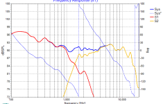
Yes that did boost my HF about 3db before my roll off (first pic attached). I think I like this due to the fact I have a L-Pad knob and can lower my HF if needed.Juhazi, one of the drivers in question is a compression driver firing through a horn composed of the 12" driver's cone. You can estimate the off axis of direct radiators with a pistonic simulator like the edge, but not horns.
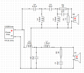
For the OP, if you put a small capacitor (maybe 1.5uf) in parallel with the 7.5 ohm resistor in AllenB's crossover, you may be able to lift teh high frequencies somewhat. Simulate and see what happens.
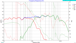
One question I had was...if you look at the second attachment (green line), with this design aren't I crossing over above the cone breakup? I assumed that 5db peak at 2k was the woofer breaking up...is that right?
Once again...thank y'all so much for the input!
Attachments
If I go into the detail I didn't before, since you're starting the tweeter radiating at an angle less than the baffle it means there is only one place it works to cross, and that's somewhere between 1 and 2kHz. The only way to be certain is to take polar measurements.
Ideally you would lower the breakup region to the point where it's not only flat, but further down until it's inaudible.
Ideally you would lower the breakup region to the point where it's not only flat, but further down until it's inaudible.
I see. But isn’t the new crossover point in the above graphs roughly 3300Hz and not between 1-2k?
I ordered a measurement mic and a DATS today btw 🙂
I ordered a measurement mic and a DATS today btw 🙂
I didn't mean to mislead you but I may have, I didn't have much time to spend on it the other day. I wanted to make the point that the response could be created, what it could look like, what the slopes could look like and to show the use of phase in Xsim.isn’t the new crossover point in the above graphs roughly 3300Hz and not between 1-2k?
I can't seem to figure out how to show phase in xsim.
I am going to pull measurements later this week, but in the mean time I am trying to get better at tweaking xo in xsim. I tried a 4th order and found it easier to get the XO point closer to where I want it. Is this a reasonable response? I am learning more and more each day🙂 Thanks again
I am going to pull measurements later this week, but in the mean time I am trying to get better at tweaking xo in xsim. I tried a 4th order and found it easier to get the XO point closer to where I want it. Is this a reasonable response? I am learning more and more each day🙂 Thanks again
Attachments
Ok so I took measurements and combined them and now have actual measurements for the woofer and the tweeter. I have attached the frd files. I can't figure out the 80Hz dip but I am going to chalk it up to cabinet issues.
As far as the crossover is concerned can someone let me know if this looks acceptable? Keep in mind I have a L-pad knob and can lower the tweeter level to exactly where I need it.
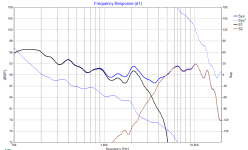
This first set of images is a 2nd order. To me the response seems acceptable but the phase of the drivers (if I'm reading it right) is not.


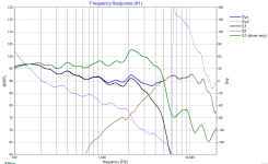
The next set is a fourth order, the frequency response seems similar and also acceptable (to me) and the phase seems to more desirable than the second order.


Feedback please 🙂
As far as the crossover is concerned can someone let me know if this looks acceptable? Keep in mind I have a L-pad knob and can lower the tweeter level to exactly where I need it.
This first set of images is a 2nd order. To me the response seems acceptable but the phase of the drivers (if I'm reading it right) is not.
The next set is a fourth order, the frequency response seems similar and also acceptable (to me) and the phase seems to more desirable than the second order.
Feedback please 🙂
Attachments
Arggg...time limit for editing posts has gone by. The data for the 4th order above is not correct....one of my inductors wasn't properly setup. The correct ones are below. Given that I can use the L-pad it looks good to me (no need to bring the tweeter down any further). The phase looks good too right? They are following the same pattern at the xo point...I'm assuming that's what you want. xsim file attached


Attachments
Last edited:
If you measured indoors in a room of typical size at something like a meter, most of the low frequency response (below about 300 Hz) becomes highly influenced by room effects with long gating/time windows. There are ways around that (primarily true nearfield measurement), but they take more steps. You don't have to go to those lengths to get a good result, it's just something to be aware of so you don't chase the wrong things. Moving the microphone or speaker several feet to a different distance or height will often show those issues.the 80Hz dip
Also, I'd design with the L-pad set to something more like flat response, since that's where you're likely to wind up. It's not as easy to judge the crossover transition region when one driver is at a significantly higher SPL than the other.
Last edited:
Yes I am just going to order a bunch of different resistor values and a couple cap values and just play around with it. Now that I have a mic and somewhat know how to use REW I feel much more comfortable doing tweaks on the fly. Thanks!Also, I'd design with the L-pad set to something more like flat response, since that's where you're likely to wind up. It's not as easy to judge the crossover transition region when one driver is at a significantly higher SPL than the other.
FWIW, I calc'd a 1298 Hz averaged polar response XO point.Any idea about off-axis behaviour?
So I haven't started learning about off-axis behavior yet...can you explain further what you mean by this? Are you saying that 1298 Hz would be the most desirable xo point?FWIW, I calc'd a 1298 Hz averaged polar response XO point.
I assume I need to take off-axis measurements...but how to I incorporate that into cabinet and/or xo design? Is there a guide on this site that explains the process?
You have been doing this DIY speaker thing for a while, probably built a couple of proven designs from people like Zaph , Troels Gravesen, Paul Carmody or any number of other successful designers.
Perhaps you started out like me, cobbling together random drivers with off the shelf or textbook crossovers, but never quite worked out why they didn’t work out as well as you imagined. You bought books like David Weems' “Designing Building and testing your own speaker system” and Vance Dickasons "Loudspeaker Design Cookbook" and have decided it is...
Perhaps you started out like me, cobbling together random drivers with off the shelf or textbook crossovers, but never quite worked out why they didn’t work out as well as you imagined. You bought books like David Weems' “Designing Building and testing your own speaker system” and Vance Dickasons "Loudspeaker Design Cookbook" and have decided it is...
- wintermute
- Replies: 26
- Forum: Multi-Way
https://kimmosaunisto.net/
https://kimmosaunisto.net/Software/VituixCAD/VituixCAD_help_20.html
We can give this thread a try. The idea is that Vituixcad newbies who have a fair understanding of speaker making concepts but are amatuers with Vituixcad can ask away for basic help. It might even help keeping it as an accessible source for a Vituixcad manual.
Of course we would like the veterans to keep an eye out that the right thing is taught so hoepfully they subscribe to the thread and keep checking in.
Of course we would like the veterans to keep an eye out that the right thing is taught so hoepfully they subscribe to the thread and keep checking in.
- Trdat
- Replies: 149
- Forum: Software Tools
etc.
Best compromise, i.e. the drivers aren't a good match WRT polar response, so found the closest for each and averaged that.So I haven't started learning about off-axis behavior yet...can you explain further what you mean by this? Are you saying that 1298 Hz would be the most desirable xo point?
I assume I need to take off-axis measurements...but how to I incorporate that into cabinet and/or xo design? Is there a guide on this site that explains the process?
Back in '68 when Altec still 'ruled', I was told during a plant tour that I would learn all I needed to know about the basics of speaker design in general and multiple driver design in particular if I reversed engineered the W.E./Lansing/Altec 755, a three way single driver [tri-ax] = a single molded diaphragm with two mechanical XOs and I did [at least to my satisfaction] once I'd learned enough of the underlying physics.
Anyway, 'sound is round', i.e. an exponential expansion [1/f] = octave spread, so to find a driver's acoustical half power/XO point [-f3D] we need to know where it's no longer pistonic = the effective diameter of the VC, so a 'close enough' frequency [VCf] for speaker design is its published dia., then -f3D = sqrt [VCf * Fs] and if more XO points, then 2-f3D = sqrt[VCf *-f3D], 3-f3D = sqrt[VCf * 2-f3D], etc..
Most (practically all) loudspeaker driver manufacturers publish at least up to 30deg off-axis responses. If these are not available, driver¨s effective Sd is told (and you can calculate diameter)
Driver's nominal diameter is often the frame, not the cone+half roll of surround)
Also the baffle and cone/dome profile will affect spl response behaviour details, that's why off-axis measurements installed in the box in question are so important
https://www.seas.no/index.php?optio...&catid=52:prestige-coaxial-drivers&Itemid=241

https://www.products-peerless.com/en/transducer/141
Driver's nominal diameter is often the frame, not the cone+half roll of surround)
Also the baffle and cone/dome profile will affect spl response behaviour details, that's why off-axis measurements installed in the box in question are so important
https://www.seas.no/index.php?optio...&catid=52:prestige-coaxial-drivers&Itemid=241
https://www.products-peerless.com/en/transducer/141
- Home
- Loudspeakers
- Multi-Way
- Coaxial Speaker Build - Crossover advice needed