Are you using the OM5284 now?yes, my servo board works. In practice it fits very well as HECD-019a.
Are you using the OM5284 now?
I wanted to ask you a question, do you know if the service manual for the servo board for CDM PRO Vau1252 is available? I have a problem with a Mark Levinson n37, the drawer does not open and close and the problem is on the servo board, there is some component short circuit.
I think the drawer is nothing to do with the CD-PRO, the DSA of CD-pro, even don't have the open close command!
CD6000 no need any DSA, the DSA controller also control the SAA ic by I2C, and convert the command to DSA for MCU.Dear Sergio, I am working on an Audionet ART G2, based on Marantz CD63 or CD6000. As far as I can see the communication pins which are labeled AuxBack, AUX1 Data and AUX3STB on HECD-019A are labeled DSA ACK, DSA DATA and DSA STRB on the Audionet connector. Would your board support this kind of communication?
Best regards from Germany
Benedikt
Yes, exactly, the drawer opening and closing controls are external to the servo board.I think the drawer is nothing to do with the CD-PRO, the DSA of CD-pro, even don't have the open close command!
However there is some "interference" between the servo and the player controller.
But according to the tests done by another forum user there is an anomaly in the board, there are 390 ohms at a specific pin that shouldn't be there, there is certainly a short circuit somewhere that creates problems with the drawer controls.
For whom could be interested Aliexpress sells this kit:
https://it.aliexpress.com/item/1005...t_main.10.5ccc3696qinrmQ&gatewayAdapt=glo2ita
It's a beautiful servo board, DSA compatible for CDM12 OPU, could be purchased with or without controller and brushless motor and it's full functional!
https://it.aliexpress.com/item/1005...t_main.10.5ccc3696qinrmQ&gatewayAdapt=glo2ita
It's a beautiful servo board, DSA compatible for CDM12 OPU, could be purchased with or without controller and brushless motor and it's full functional!
can you share the this gerber?
really interesting, it is possible to find these CDT612 PHILIPS MICROCONTROLLER FOR CD SYSTEMS, QFP44 RETRO SOUND SYSTEM UKSTK: https://www.ebay.it/itm/225889157696 but is there a diagram of a player that uses it? and is it possible to use your printed circuit instead?
In China Taobao, you can find a lot !!! That just because the IC was design for VCD which was invented by Chinese! The VCD just using the CD module from PHILIPS, CDT713 is for 3 disc , 612 is for 1 disc, but the 713 also can work with 1 disc, they all use DSA protocol like the CDPRO, just a small different.
I am now a CD player designer, I know a lot, about these things.
I am now a CD player designer, I know a lot, about these things.
Attachments
The problem is understanding the schematic and the laser and the transport that the chip you buy uses. When the SAA starts, the chip downloads the initialization structure that MUST be related to the characteristics of the mechanics. So buying the chip means nothing. Then the CD10 added other advanced features that could set the registers and allow the laser to better adjust the current to get a focus. But you have to find the schematic for those chips, you have to have a schematic that the chip is linked to, including the version of the chip, otherwise it is useless, it would be much better to write the code in i2C directly and do a reverse engineering of the mechanical configuration data by mechanics. Or manage to find ESS Technology code on Chinese archives, I myself found something a long time ago on PUDN. There was a Russian guy who had done an excellent and similar work on the CEC mechanics, great talent.
Hi, given your experience, and therefore given that you are a CD Player designer, is there a way to send the commands directly to the servo board without using a proprietary firmware? For example, send the commands PLAY PAUSE STOP etc etc ... via the STB DATA ACK pins, or directly to the SAA7327/7372 via the SDA protocol therefore the 6-pin CD906 connector therefore to the SDA SCL SILD RAB SILD RST GND pins?In China Taobao, you can find a lot !!! That just because the IC was design for VCD which was invented by Chinese! The VCD just using the CD module from PHILIPS, CDT713 is for 3 disc , 612 is for 1 disc, but the 713 also can work with 1 disc, they all use DSA protocol like the CDPRO, just a small different.
I am now a CD player designer, I know a lot, about these things.
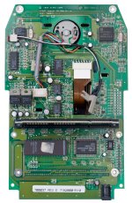
Servo controller HECD-019A:
Example, reading the codes of the remote control that sends data to the IR receiver by analyzing the play code is...
Ready to receive IR codes...
Protocol: 17
Command: 0x35
Address: 0x14
RAW: 0x1535
---
Protocol: 17
Command: 0x35
Address: 0x14
RAW: 0x1535
---
Protocol: 17
Command: 0x35
Address: 0x14
RAW: 0x1D35
---
Protocol: 17
Command: 0x35
Address: 0x14
RAW: 0x1D35
---
So what is the command to send directly to the servo board then to the P87C58 microcontroller or to OM5284?
Using a logic analyzer this is what sends the firmware to the 87C58 connected to the AUXSTB AUXDATA, AUXACK pins, highlighted in yellow the IR code sent by the remote control.
We can finally clarify what is actually sent on the AUXDATA line, what code represents the IR command and how to replicate it correctly.
In the first image you can see a classic Philips DSA type parallel transmission sequence:
AUXSTB (D0): acts as a clock or strobe: each transition signals a new bit or a new byte.
AUXDATA (D1): contains the serial data bits to be transmitted.
AUXBACK (D2): is probably an acknowledge line (ACK) or a response from the module.
IR RECEIVER (D3): confirms the reception of the signal from the remote control.
The output code is not pure RC5 or NEC. The internal microcontroller converts the received RC5 command (e.g. 0x35) into a sequence of parallel data transmitted as a DSA command.
Example: "Play" command
When the remote control sends the RC5 code 0x35:
The microcontroller transmits on the AUXDATA line the sequence that, according to the DSA datasheet, is:
Play = 0x01h + Parameter (e.g. 0Ah for track 10)
→ So: 01 0A
In your signal it seems at least 2 bytes are sent, and they are probably:
First byte (opcode): 0x01 = Play title
Second byte (param): 0x0A = track 10 (default if the firmware does not change value)
So the IR code 0x35 is only used to:
Activate the "Play" function in the microcontroller firmware.
The firmware then generates the complete DSA codes (opcode + parameter) on the AUXDATA and AUXSTB lines.
So what code do you need to send "Play" manually?
If you want to simulate directly via Arduino (without using the remote control), you need to send:
AUXDATA = 0x01; // command "Play title"
AUXDATA = 0x0A; // parameter: track 10
With AUXSTB changing from H to L at each byte.
Conclusion:
The IR code 0x35 is not the real DSA command, but a trigger for the microcontroller that then generates the real DSA command.
If you want to control the mechanics directly, you should bypass the microcontroller and generate the AUXSTB + AUXDATA signals via Arduino or other micro.
So, given your experience, the question is: is it possible to send commands directly to the SAA7372/SAA7327 CD decoder digital servo processor bypassing the various P87C58 OM5284?
Last edited:
I have successfully extracted the contents of the .sal file from the Logic 2 software. The binary files correspond to the various digital channels analyzed, while the meta.json file contains the project metadata (channel names, sampling, duration, etc.).
I will now analyze:
the meta.json file to understand which signal each channel corresponds to (e.g. AUXSTB, AUXDATA, AUXBACK, IR RECEIVER, etc.),
the binary segments to identify the command sent for each button (Play, Pause, Stop).
Proceed with the analysis of the meta.json file.
I have analyzed the meta.json file of your Logic 2 project, and now we have the complete correspondence between digital channels and signal names:
Channel NameDescription
D0 AUXSTB Command strobe signal
D1 AUXDATA Serial data sent to the CD controller
D2 AUXBACK Response/ack from the controller
D3 IR RECEIVER IR receiver output
D4 Channel 4 Free or unlabeled
D5 Channel 5 Free or unlabeled
Now that we have the channels clear, I can:
decode the sequence sent on AUXDATA during a command like "Play",
compare it to what is expected in the datasheet (e.g. command 01h + parameter xx for "Play Title"),
deduce the complete code sent via AUX.
Now I would like to try to analyze the first command transmitted (e.g. the one related to the first "Play") to determine the real data packet sent (opcode + parameter).
Attached is the log using the Logic 2 software so just download the software from the site to view the file content.
Were sent 4 commands, Play - Pause - Play - Stop.
Attachments
I'm picking up a kit from AliExpress, they claim I have to run the cdm12 with CD7-II and I'll simply connect a mechanic to it. Working only in i2C will make things clearer, I'll just look at the init, I saw there is an automatic focus command, which if launched the system creates the oscillation of the lens up and down, and if it finds the disc it changes the state, then there is a start command and starting from the center and the qsubs that correspond to the TOC will be read, and then according to the redbook the groove launch command must be given and they must be counted... all a real mess, but once launched, the disk turns and the lens follows the track. If everything is coordinated with the right parameters, the or in analog. It will be interesting to reverse engineer all these steps. The 4wire format is more complex to read from a sniffer, but the i2C has a master and a slave, and is easier to decode. This is the only way this work can be tackled.
I don't need any reverse R&D, I have the original PHILIPS code, I can directly control CD7 and CD7 II through I2C, and I also have the code to control CD player through DSA, but these are no longer of commercial value, because it is difficult to batch the OPU of CDM12.The problem is understanding the schematic and the laser and the transport that the chip you buy uses. When the SAA starts, the chip downloads the initialization structure that MUST be related to the characteristics of the mechanics. So buying the chip means nothing. Then the CD10 added other advanced features that could set the registers and allow the laser to better adjust the current to get a focus. But you have to find the schematic for those chips, you have to have a schematic that the chip is linked to, including the version of the chip, otherwise it is useless, it would be much better to write the code in i2C directly and do a reverse engineering of the mechanical configuration data by mechanics. Or manage to find ESS Technology code on Chinese archives, I myself found something a long time ago on PUDN. There was a Russian guy who had done an excellent and similar work on the CEC mechanics, great talent.
The new product I am designing now uses CD18 and OPU is the new OPU, and their actual effect is better than CD7+CDM12.
CDM12 is just my personal hobby, because when I first entered the audio industry, it was because of CDM12.
Direct I2C writing is possible, but its code will be more complicated, involving the servo processing process, not just commands, and the DIY is difficult to realize. That's why PHLIPS made these chips. I have these codes, but this is the property of the company and I can't give it to you. Here is a code for controlling cd through DSA, which was downloaded online many years ago. This has some reference.Hi, given your experience, and therefore given that you are a CD Player designer, is there a way to send the commands directly to the servo board without using a proprietary firmware? For example, send the commands PLAY PAUSE STOP etc etc ... via the STB DATA ACK pins, or directly to the SAA7327/7372 via the SDA protocol therefore the 6-pin CD906 connector therefore to the SDA SCL SILD RAB SILD RST GND pins?
Servo controller HECD-019A:
Example, reading the codes of the remote control that sends data to the IR receiver by analyzing the play code is...
Ready to receive IR codes...
Protocol: 17
Command: 0x35
Address: 0x14
RAW: 0x1535
---
Protocol: 17
Command: 0x35
Address: 0x14
RAW: 0x1535
---
Protocol: 17
Command: 0x35
Address: 0x14
RAW: 0x1D35
---
Protocol: 17
Command: 0x35
Address: 0x14
RAW: 0x1D35
---
So what is the command to send directly to the servo board then to the P87C58 microcontroller or to OM5284?
Using a logic analyzer this is what sends the firmware to the 87C58 connected to the AUXSTB AUXDATA, AUXACK pins, highlighted in yellow the IR code sent by the remote control.
We can finally clarify what is actually sent on the AUXDATA line, what code represents the IR command and how to replicate it correctly.
In the first image you can see a classic Philips DSA type parallel transmission sequence:
AUXSTB (D0): acts as a clock or strobe: each transition signals a new bit or a new byte.
AUXDATA (D1): contains the serial data bits to be transmitted.
AUXBACK (D2): is probably an acknowledge line (ACK) or a response from the module.
IR RECEIVER (D3): confirms the reception of the signal from the remote control.
The output code is not pure RC5 or NEC. The internal microcontroller converts the received RC5 command (e.g. 0x35) into a sequence of parallel data transmitted as a DSA command.
Example: "Play" command
When the remote control sends the RC5 code 0x35:
The microcontroller transmits on the AUXDATA line the sequence that, according to the DSA datasheet, is:
Play = 0x01h + Parameter (e.g. 0Ah for track 10)
→ So: 01 0A
In your signal it seems at least 2 bytes are sent, and they are probably:
First byte (opcode): 0x01 = Play title
Second byte (param): 0x0A = track 10 (default if the firmware does not change value)
So the IR code 0x35 is only used to:
Activate the "Play" function in the microcontroller firmware.
The firmware then generates the complete DSA codes (opcode + parameter) on the AUXDATA and AUXSTB lines.
So what code do you need to send "Play" manually?
If you want to simulate directly via Arduino (without using the remote control), you need to send:
AUXDATA = 0x01; // command "Play title"
AUXDATA = 0x0A; // parameter: track 10
With AUXSTB changing from H to L at each byte.
Conclusion:
The IR code 0x35 is not the real DSA command, but a trigger for the microcontroller that then generates the real DSA command.
If you want to control the mechanics directly, you should bypass the microcontroller and generate the AUXSTB + AUXDATA signals via Arduino or other micro.
So, given your experience, the question is: is it possible to send commands directly to the SAA7372/SAA7327 CD decoder digital servo processor bypassing the various P87C58 OM5284?
View attachment 1462376
View attachment 1462377
Attachments
- Home
- Source & Line
- Digital Source
- Clone SERVO CD HECD-019A for PHILIPS CDM12.1