好久不见,DSA相对于I2C控制更简单。伺服参数要很多设备检测。现在国内流行的都是VCD的源代码。很多代码没处理,前进 后退 没静音。你新做的板子还有吗?发给我试试,最近比较有空。我邮箱cndiyclub@hotmail.com
Long time no see, DSA is simpler than I2C control. Servo parameters need to be detected by many devices. Now the popular ones in China are the source code of VCD. A lot of code is not processed, forward backward is not muted. Do you still have your newly made board? Send it to me to try, I have been more free recently. I cndiyclub@hotmail.com my email
Long time no see, DSA is simpler than I2C control. Servo parameters need to be detected by many devices. Now the popular ones in China are the source code of VCD. A lot of code is not processed, forward backward is not muted. Do you still have your newly made board? Send it to me to try, I have been more free recently. I cndiyclub@hotmail.com my email
Do you know this item? could it be functional as HECD-019A?
Paolo
https://www.99go.com/item/13766691691
Paolo
https://www.99go.com/item/13766691691

In this last month, a few ideas have come to my mind. Redesign the mechanics. For example, the mechanical drawer stepper motor controlled by the adapter board elaborated by HEC-019, developed with built-in arduino atmega328 and 3 variants. One for A4988 motor operator, one with 2 SRA-12VDC-CL relays, one with 2 G6K-2F-Y DC12 micro relays. You will say if I'm crazy but the idea was born with the logic of using your project at will. All three have built-in DC voltage regulation circuits: one 12V, two 5V, and one 3.3V.This is the CDM12 I made back then, without DSA control. Control I2C directly with the MCU. The output uses DIT 4192 as a digital output.
Logically, the board in question will then be connected to the Servo Board HEC-019.
Bottom Layer with Atmega328
Top Layer with A4988
Top Layer with Relè SRA-12VDC-CL
Top Layer with Micro Relè G6K-2F-Y DC12
The output uses DIT 4192 as a digital output.
in my project i use DIT 4096. downstream from the motherboard a AM26LS31CD with the possibility of the by-pass.
from the datasheet the differences between the DIT4192 (192kHz) and DIT4096 (96kHz)
the connection pins are practically identical
hello cac liuI just tested it and I made a big discovery! The board using SAA7372 uses I2C communication to be fully compatible with SAA7327! This is something I've always wanted to test, tried it today, it's the same! In other words, OM5284 can replace your P87C58! But there is a difference in wiring because the OM5284 uses SILD and RAB, just like the circuit of the CDT-713 I attached! Like datasheet, the SAA7327 is just adding some new registers to the SAA7372! The software is compatible!
can you send me the gerber file or from where did you get the board i want to compare with mine. I'm having problems, I can't get it to work.
Thanks
thanks for the file!Here it is!
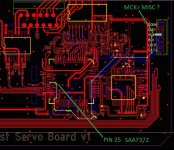
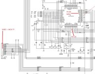
I checked your gerber project and compared it with the CD7 schematic (DSA 1disc)-3.PDF you sent and I find an error. Pin 25 of SAA7372 on the schematic is not connected, in your Gerber file it is connected to pin 25 of SAA7372 at MCK output connector. What would MCK be, is it the MISC output, file "CD7 (DSA 1disc)-3.PDF"? Why is it connected to Pin 25 of SAA7372? Do you have a different outline of your project?
Indeed Pin 44 SAA7372 MISC in your gerber file is not connected.
Attachments
My cd8 do not using MCLK, it got PLL on DAC board, and it's very clear for the clock, CL16 for 16.9344M, CL11 for 11.2896M.
OK thanks.
All very clear.
the schematics is not my board's schematics, it is a VCD's schematics. VCD using the MISC for other things.
Do you have the schematic you used to make your project?
in addition to the fact that I wanted to understand the "setup" connections and the operation of this servo board, since I am a fan of the old Philips CDM0/1 mechanics, I have many of them, I am collecting the schematics of all the philips mechanics to have a database the as complete as possible.what is the problem? you have the OM5284 which marked a CDT713 on it?
For example, in the case of HECD-019A there are no schematics, or at least I have never found any on the internet.
- Home
- Source & Line
- Digital Source
- Clone SERVO CD HECD-019A for PHILIPS CDM12.1