datasheet say-
7.15
Communication on the microcontroller interface can be set-up in two different modes:
•4-wire bus mode: protocol compatible with SAA7345 (CD6) and TDA1301 (DSIC2) where:
– SCL = serial clock
– SDA = serial data
– RAB=R/W control and data strobe (active HIGH) for writing to decoder registers 0 to F, reading status bit selected via decoder register 2 and reading Q-channel subcode
– SILD =R/W control and data strobe (active LOW) for servo commands.
•I2C-bus mode: I2C-bus protocol where SAA7327 behaves as slave device, activated by setting RAB = HIGH and SILD = LOW where:
–I2C-bus slave address (write mode) = 30H
–I2C-bus slave address (read mode) = 31H
– Maximum data transfer rate = 400 kbits/s.
It should be noted that only servo commands can be used therefore, writing to decoder registers 0 to F, reading decoder status and reading Q-channel subcode data must be performed by servo commands.
Last edited:

file to open with LOGIC 2 software
https://www.saleae.com/downloads/
the reading was carried out on the SAA7327 on pins 39 - 40 - 41 - 42 at power up, power ON CD, mechanical movement of the axes.
https://www.saleae.com/downloads/
the reading was carried out on the SAA7327 on pins 39 - 40 - 41 - 42 at power up, power ON CD, mechanical movement of the axes.
Attachments
Last edited:
I'm sorry dxx573k , but I'm a beginner in programming, what data should I collect and where should it be entered. In the servo board there is a Philips P87C58 Eprom, should they be inserted in this Eprom? How should a program be compiled? Unfortunately, I'm not good at programming. Have patience unfortunately I'm not practical.
Last edited:
I cant write a code for your. The original microcontroller is 8051 core. The Arduino/Atmega is more easy for beginners, but anyway, you must learning basic concepts of programming. Dont fear - its near to standart school knowledge. I am not a programmer to.
Tonight i continue work whith you data in initialisation part.
first of all - get any Arduino board and try to blink LED.
Tonight i continue work whith you data in initialisation part.
first of all - get any Arduino board and try to blink LED.
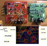
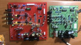
I understand that you cannot write the code for me, indeed, thank you very much for your willingness to help me solve the problem but above all to learn to code. But I don't understand a concept. If the servo code is stored in an EPROM soldered to the CDM controller. What needs to be done. Bypass the Eprom with the servo board initialization parameters and create a complete code for the controller, in my case it would be a copy of the MUSICAL FIDELITY A3.5 CD player with PIC16F88 controller in memory on the CD player motherboard. This is my doubt. My idea was to adapt the mechanical board and the servo to be used on all CD players produced with this Philips logic. This is the reason for the possible copying of the P87C58 memory but I understand that this is not possible to do perhaps because the memory is not readable. I did tests reading the Philips Eprom and it seems to read but when writing to a new P87C58 and soldered on the servo board it doesn't work. I don't know if I explained myself.
P87C58 is not EEPROM, its microcontroller whith EEPROM.

its may be encripted firmware -
"Encryption Array
Within the EPROM array are 64 bytes of Encryption
Array that are initially unprogrammed (all 1’s). Every
time that a byte is addressed during a verify, 6 ad-
dress lines are used to select a byte of the Encryp-
tion Array. This byte is then exclusive-NOR’ed
(XNOR) with the code byte, creating an Encryption
Verify byte. The algorithm, with the array in the un-
programmed state (all 1’s), will return the code in its
original, unmodified form. For programming the En-
cryption Array, refer to Table 4 (Programming the
EPROM)"
P87C58 is in the middle between dump lo-level SAA7327 and key control/display PIC16F88.
SAA7327 controll needs continiously supervisering from up-level controller whith 2-3ms delay.
SAA7327 controll needs continiously supervisering from up-level controller whith 2-3ms delay.
I forgot... the PIC16F88 memory on the motherboard of the reader I was able to read it and it was written on a new PIC. so as mentioned the firmware is readable but is in HEX format. So I guess it can't be edited.
so you are telling me that the PIC16F88 is nothing but the memory where the control data of what is shown on the display is stored.
as for reading and writing philips P87C58 micro controller. I used this XGPRO software and this programmer. In the read and write configuration there are some points to select, as you can see in the sub-tables " ENCRYPT. TB" and "CONFIG"

I haven't actually tried to read or write by changing the parameters on "CONFIG" . Could this be the problem of the non-functioning of the new P87C58 programmed by me?


I haven't actually tried to read or write by changing the parameters on "CONFIG" . Could this be the problem of the non-functioning of the new P87C58 programmed by me?
Last edited:
okay. so at this point let's forget the Philips chip and let's try with Arduino and Atmega chip since it's always a QFP-44 chip only that I imagine the scheme and the pinout are definitely different so I'll have to modify the servo board.
as far as Arduino is concerned, I have already done simple usage tests in the past, and that is trying to turn on and off simple leds or relays. So I would have Arduino UNO and Arduino MEGA 2560. So if you want, let's try to develop something.
as far as Arduino is concerned, I have already done simple usage tests in the past, and that is trying to turn on and off simple leds or relays. So I would have Arduino UNO and Arduino MEGA 2560. So if you want, let's try to develop something.
Last edited:
Working with an Arduino is not too difficult:
I think there aren't any libraries, but perhaps thete are for 3-state bus handling. Anyway:
Set the initialization for the necessary pins (mode select, etc). Define the bus pins.
Within the loop:
Set the bus pins as input, read the values.
Process according to the operating modes (that is four routines since you identified four modes, right?)
Each routine gives an output value, but only one routine is selected according to the input conditions.
Perhaps the previous value of the output pins also plays a role - if not it is better.
Set the I/O pins as output, and place the output values of the routine onto them.
Now the timing: make sure your loop last exactly the necessary time.
Terminate the loop.
I know it sounds simple, you only need a protocol analysis to see the relation between the inputs and outputs on the bus. There must be also direction control on a separate pin.
- Home
- Source & Line
- Digital Source
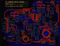
- Clone SERVO CD HECD-019A for PHILIPS CDM12.1