Hi alpefesounds better, but has a high distortion before 20khz, so I dismissed it, although the measurements do not sound, dictate the ears.
Which one is better for you?...i look at your post at the beginning but I don´t find some distortion 20khz measurements?
kr
chris
I have ordered two Muses 02 and one OPA828 x2 with Adapter. We will see and hear...
I have changed the 100 Ohm resistors to 22 Ohm. Done in seconds.
Ok, 100nf at the big Capicitors are missing. Instead of the ceramic caps i soldered glimmer in.
Perhaps an other output stage with BD139/140 will make something better. The JC2 Clone has such an output stage, thats right. If heat sinks are needed on the C3850 board i can make the pcb bigger. In the moment it is similar from the size to the Mofi board.
I wiil post the new gerber files on this weekend.
I have to carry my equipment for our regular table in the evening in my car. (exept the microwave) 🙂
Attachments


sorry I was wrong on the JC2 clone (bad) averages, they are not that bad, but worse than the other one or the C-3850.
https://www.diyaudio.com/community/threads/clon-jc2.416747/#post-7773316
https://www.diyaudio.com/community/threads/clon-jc2.416747/#post-7773316
I have ordered two Muses 02 and one OPA828 x2 with Adapter. We will see and hear...
I have changed the 100 Ohm resistors to 22 Ohm. Done in seconds.
Ok, 100nf at the big Capicitors are missing. Instead of the ceramic caps i soldered glimmer in.
Perhaps an other output stage with BD139/140 will make something better. The JC2 Clone has such an output stage, thats right. If heat sinks are needed on the C3850 board i can make the pcb bigger. In the moment it is similar from the size to the Mofi board.
I wiil post the new gerber files on this weekend.
I have to carry my equipment for our regular table in the evening in my car. (exept the microwave) 🙂
Nice Power Amp.I have ordered two Muses 02 and one OPA828 x2 with Adapter. We will see and hear...
I have changed the 100 Ohm resistors to 22 Ohm. Done in seconds.
Ok, 100nf at the big Capicitors are missing. Instead of the ceramic caps i soldered glimmer in.
Perhaps an other output stage with BD139/140 will make something better. The JC2 Clone has such an output stage, thats right. If heat sinks are needed on the C3850 board i can make the pcb bigger. In the moment it is similar from the size to the Mofi board.
I wiil post the new gerber files on this weekend.
I have to carry my equipment for our regular table in the evening in my car. (exept the microwave) 🙂

@Kleinhorn
A couple thoughts about the smt opamp in the layout. An 0805 size 100nf/50V cap could be placed by the opamp at pin-4 and pin8.
The footprint suggests a no-lead package. If soldering by hand with a soldering iron, you may want to extend the pins outwards so that they are accessible with the soldering tip. If needed, shave the pads or use circular pads on the DIP opamp footprint to make room.
if you want to talk about JC2 , in the other thread so as not to mix.
https://www.diyaudio.com/community/threads/clon-jc2.416747/#post-7773316
https://www.diyaudio.com/community/threads/clon-jc2.416747/#post-7773316
It seems to perform much better with more feedback. It really don't know what the heck I'm doing with LTspice, but with the 1000R feedback resistor (R3) there is still low distortion at 2.0V. Is this correct?
Attachments
@nattawa
I can give more space with other pads, thats possible. There are 100 nf at pin 4 and 8. You cant see on the last picture. Or others ?
It is possible to make 2 different gerber files, one with the "normal" OPA and the other with SMT. Perhaps the better solution..
Peter
I can give more space with other pads, thats possible. There are 100 nf at pin 4 and 8. You cant see on the last picture. Or others ?
It is possible to make 2 different gerber files, one with the "normal" OPA and the other with SMT. Perhaps the better solution..
Peter
Attachments
Last edited:
hifiamps I think you're correct about the distortion decreasing if you increase the feedback resistor to 1k. Driving a 470R feedback resistor from an output stage with a 1mA quiescent current is a bit optimistic, to say the least. I'd increase the 470R feedback resistor R27 to 4.7k and the 100R resistor R29 that it joins to from 100R to 1k. The part numbers refer to Peters schematic in my post #177. If anyone is thinking of trying the C3850 with heatsinked BD139/140 at high current I'll need to work out some new resistor values for the output stage.
@Kleinhorn
I did see them through-hole caps by the DIP package, and they are as compact placement as you can get. With SMD option you can do a lot better in minimizing the rail decoupling loop area, or parasitic inductance. This can be helpful for some opamps. Modern opamps even designed for audio can have gain*bandwidth far out to 50MHz or higher. By putting smd caps close by the smd opamp, the decoupling loop area becomes probably 1/3 or less that in the case of DIP opamp. Not saying they will certainly make a difference, it's more about have them and not need them vs not have them and need them.
I did see them through-hole caps by the DIP package, and they are as compact placement as you can get. With SMD option you can do a lot better in minimizing the rail decoupling loop area, or parasitic inductance. This can be helpful for some opamps. Modern opamps even designed for audio can have gain*bandwidth far out to 50MHz or higher. By putting smd caps close by the smd opamp, the decoupling loop area becomes probably 1/3 or less that in the case of DIP opamp. Not saying they will certainly make a difference, it's more about have them and not need them vs not have them and need them.
Everything you say about decoupling is spot on nattawa, but I've used just a pair of film caps with some very fast opamps ( LM6171 ) on many occasions in the past without issue. This is for audio of course, for rf your suggestions would be mandatory. Let me draw your attention to post #251 again - upping the values of the resistors in the feeback loop is essential for low distortion. There are very few opamps that can drive a 470R+100R load at low distortion and the ones that can have quiescent currents of more than 1mA.
Hi peter(I dont know your real name...)
Do you you think it is possible to hear your changes ? I have a scope and function generator, but dont know tu use it...electronic newbie in some cases.😎
I have only my ears to verify, subjective
Peter
the best explanation how to use a scope !
thanks dave
DAVE - scope
kr
chris
Hi...
No way....i spent over two hours now to find a way to connect a standing alone OPA with thermal pads on the pcb properly.
Kicad only accept the red tracks "F_cu", on one side of the pcb to connect this OPA. It seems not possible to find a way to connect the tracks only on this side of the pcb. I have one track i can't connect without a crossing.
I have to give that up...its against tht concept of this pcb.
What is to do? One gerberfile exists with an footprint for one dip8 ic. One gerberfile i can upload for an OPA with thermal pad and dip8.
@chermann
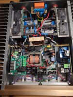
I have taken a picture of my goldmund clone. Yesterday morning the amp worked fine at home. In the evening at regulars table it worked only on one channel, failure with one speaker protection. The voltage the connection i guessed.
I had expanded and connected to my laboratory power supply, all ok. Built in and it works....😳
What the f.....
No way....i spent over two hours now to find a way to connect a standing alone OPA with thermal pads on the pcb properly.
Kicad only accept the red tracks "F_cu", on one side of the pcb to connect this OPA. It seems not possible to find a way to connect the tracks only on this side of the pcb. I have one track i can't connect without a crossing.
I have to give that up...its against tht concept of this pcb.
What is to do? One gerberfile exists with an footprint for one dip8 ic. One gerberfile i can upload for an OPA with thermal pad and dip8.
@chermann
I have taken a picture of my goldmund clone. Yesterday morning the amp worked fine at home. In the evening at regulars table it worked only on one channel, failure with one speaker protection. The voltage the connection i guessed.
I had expanded and connected to my laboratory power supply, all ok. Built in and it works....😳
What the f.....
Attachments
Last edited:
Hi PeterSoldering iron warms up...
I have made an update to the pcb. Some tracks had to be changed to put an OPA footprint with thermal pad in. KiCad does not like that, two footprint in one.
But it seems to be no problem. I uploaded the gerber files to pcw way and it seems to be fine.
Peter
i hope you enjoy your listening sessions with your friends.!
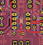
PCB- extra split supply. you have done it with a jumper but to connect the separate PSU to the PCB you wrote at D1 and D2A1 Ext+ and EXT- --> does this mean i have to connect the PSU for the OPS directly on the diode?
maybe to add an extra pin would be nice.
thanks
chris
sorry to hear that....Hi...
No way....i spent over two hours now to find a way to connect a standing alone OPA with thermal pads on the pcb properly.
Kicad only accept the red tracks "F_cu", on one side of the pcb to connect this OPA. It seems not possible to find a way to connect the tracks only on this side of the pcb. I have one track i can't connect without a crossing.
I have to give that up...its against tht concept of this pcb.
What is to do? One gerberfile exists with an footprint for one dip8 ic. One gerberfile i can upload for an OPA with thermal pad and dip8.
@chermann
I have taken a picture of my goldmund clone. Yesterday morning the amp worked fine at home. In the evening at regulars table it worked only on one channel, failure with one speaker protection. The voltage the connection i guessed.
I had expanded and connected to my laboratory power supply, all ok. Built in and it works....😳
What the f.....
so you need more amps.....sorry... 😉
😆
i am not an KICAD expert.Hi...
No way....i spent over two hours now to find a way to connect a standing alone OPA with thermal pads on the pcb properly.
Kicad only accept the red tracks "F_cu", on one side of the pcb to connect this OPA. It seems not possible to find a way to connect the tracks only on this side of the pcb. I have one track i can't connect without a crossing.
I have to give that up...its against tht concept of this pcb.
What is to do? One gerberfile exists with an footprint for one dip8 ic. One gerberfile i can upload for an OPA with thermal pad and dip8.
you can use the via (V) to make connection to the B_cu layer..maybe that helps
- Home
- Amplifiers
- Solid State
- Clon C-3850