BD139/BD140 would be ok but basically any complementary pair that you can get a good hfe match for; higher hfe is better. Lots of people have stocks of obsolete Japanese types which often match well. Don't think you'd have to parallel the emitter resistors unless you wanted a few watts of output but if they're easy to insert then why not.

Dear peter!
Thank you very much for your effort.👍 you are fast and you are willing to do it but it is not my intention to force you. sorry.
lets keep this version and make "a brake" _this is version TP_JST as you wrote.👍
STOP!
other pcb i would wait...keep the focus and the existing pcb and modifications. maybe we get other points too.
chris
for prototype everybody can try to connect a TO-126 separate and report here about the sound and modifications.BD139/BD140 would be ok but basically any complementary pair that you can get a good hfe match for; higher hfe is better. Lots of people have stocks of obsolete Japanese types which often match well. Don't think you'd have to parallel the emitter resistors unless you wanted a few watts of output but if they're easy to insert then why not.
kr
chris
Its only the two output transistors that need to be TO126. If its TO92 or TO126 then TO126 would be most flexible. The T0126 pinout is compatible with TO220 if you turn the device around, and with most Japanese TO92 types as well. Its not compatible with with the BC pinout unless you do gymnastics with the transistor leads. Having said that the BC639/640 are TO92 and have the "collector in the middle" pinout and are still available. But they are the only example I can think of.
Before i have my brake 😎
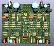
In the PCB picture BD values are missing. Corrected in the gerber file.
☕☕☕
Greets
Peter
In the PCB picture BD values are missing. Corrected in the gerber file.
☕☕☕
Greets
Peter
Attachments
Last edited:
Nice work on this board Kleinhorn, especially adding the external psu option. Thank you for sharing.

I tend to agree with Chris, most times a 'jack of all trades is a master of none'. I prefer to keep a preamp separate from a HP amp. They require different needs for best performance. 😉
I tend to agree with Chris, most times a 'jack of all trades is a master of none'. I prefer to keep a preamp separate from a HP amp. They require different needs for best performance. 😉
if anyone is interested I have a few tens of thousands of BC of different types, original PIHER the only thing is the postage that would be more expensive, the price would be of any BC of which I have 0.01eu., 100units 1 eu., so you can mate more easily,greetings.
.
.jpeg")


.
Yesterday, I have measured recently purchased BC546BTA/BC556BTA transistors and, amazingly, I have found 10 almost identical pairs (hfe about 330). I will test them in a PCB that arives soon. Although transistors from the kit are pretty consistent and have higher hfe values.BD139/BD140 would be ok but basically any complementary pair that you can get a good hfe match for; higher hfe is better.
Why all people call me by my nick ?
My name is peter or pedda. The last name you will find often on my pcb's 🙂
The "Kleinhorn" is another story. In my forum beginnings I built a little horn speaker from a company in germany, called Manhattan Acoustic , with SEAS speakers...the name "Kleinhorn"was born..😉
Peter
My name is peter or pedda. The last name you will find often on my pcb's 🙂
The "Kleinhorn" is another story. In my forum beginnings I built a little horn speaker from a company in germany, called Manhattan Acoustic , with SEAS speakers...the name "Kleinhorn"was born..😉
Peter
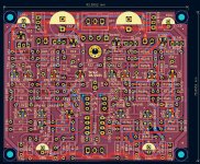
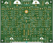
It would be useful to mark the orientation of the BD139/BD140 on the legend either with a thick bar on the metal side or explicitly write the electrode letters by the holes. Makes it easier to quickly check that you've put them in the pcb the right way round. Perhaps you might consider posting pictures of the upper and lower copper separately so that we can check the connectivity is correct - I always do this for my pcbs as I never trust any software completely.
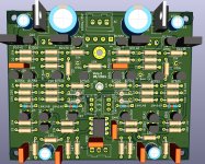
sorry Peter. The layout of the pcb looks much prettier with the new symmetrical layout - it appeals to my ocd!
As a first reply to a forum member, I use their forum 'nickname' out of respect. When a dialogue is established I will then use the preferred call name.Why all people call me by my nick ?
My forum nickname IS my real nickname and what friends call me.
I apologize, Peter from now on 😂.
I share your speculation. The output stage is biased at just under 1.5mA, and it has to drive the low-ish impedance feedback network. The result from the simulation with 20KHz sine into 5K-ohm load, at output level below 2Vpk, it works ok. At 2.2Vpk the output transistors begins to starve and are driven out of class-A operation. Distortion begins to increase rapidly as output level increases, apparently there is not much in the loop gain to fight off the cross-over distortion.It's said to be Class A, but the output transistor seems to be biased too low with only 1mA current. Any fix? Anyone understand how this circuit works? Using the 5532 alone will probably be much better as a line preamp, with much lower distortion.

In another simulation, with but the opamp remains, I had it swing to 14.5V, just below clipping, and the transient analysis returns 0 distortion.

Welcome nattawa,
thanks for your investigations. are you wiling to post here your LT spice file.
i am a noob but...
thx
chris
thanks for your investigations. are you wiling to post here your LT spice file.
i am a noob but...
thx
chris
There's an easy fix for the low quiescent current in the output devices, simply reduce the value of emitter resistors from 22R to 6R8 (4.5mA quiescent) or even as low as 2R2 (15mA quiescent) if you're feeling adventurous. Another suggestion; decreasing the value of the vas emitter resistors from 220R to 160R will up the vas current to about 5mA which will give more open loop gain and bandwidth and a bit lower distortion. Operating the output transistors further into class A would probably improve the sound as well. I've got some of the Aliexpress boards but haven't built one yet so I'll try these mods as soon as I have. Maybe nattawa could simulate these suggestions.
- Home
- Amplifiers
- Solid State
- Clon C-3850