Good one Jocko !! 😀
Good point about the SM caps too, i always wondered why they could print on SM resistors, but never on SM caps. What's the explanation for this great mystery in the electronics industry?
Good point about the SM caps too, i always wondered why they could print on SM resistors, but never on SM caps. What's the explanation for this great mystery in the electronics industry?
Lars Clausen said:With a few exceptions, the same would be the case in any SACD player. That's why we always recommend a CD player to play CD's. The PLL circuit in almost every SACD player will always be the reason it is inferior to a CD player, contradictionary to what the colorful adds from the SACD companies want you to think.
Lars, I was not talking about the PLL, that's obviously needed on a multi-format player.
As I understand, that player is cramped with video circuits.

Do they just remove the on-board video plugs (SCART, S-Video, etc.) and put the PCB on a fancy chassis?

Lars Clausen said:My suggestion is: Get a good CD player instead!
Of course.

Lars Clausen said:Audiofanatic: Please .. Be my guest, and send it to the advertising dept. of S**Y as well .. 😀
Just to let them know that we (the people) are not so dim as to believe anything they write in their ads ..
It is very likely that they fool the typical "What HI-FI?" reader, not us.
PS: Every Sony player begs for a clock.
Jocko
YESSSSSSSSSSSSSSSSSSSSSSS!!!!!!!
Your absolutly right, we know better!!!!!!!!
Thanks Lars, I'll keep you informed 😀
Carlos, you're right too, even SONY needs modding (clock's)!
Cheers,
Audiofanatic 😉
Anyway, it isn't us who are the dim ones. They write it.........they believe. We just happen to know better.
YESSSSSSSSSSSSSSSSSSSSSSS!!!!!!!
Your absolutly right, we know better!!!!!!!!
Thanks Lars, I'll keep you informed 😀
Carlos, you're right too, even SONY needs modding (clock's)!
Cheers,
Audiofanatic 😉
driver board
I'm going to have to go in there,and clean up the entire PS all around those driver boards, simply to get the best as is possible from the compromised design of the unit. I've no idea who's is better though: I find it not good to unessessarily pick on Shanling, who knows how the rest of these units (SACD Players in general) are designed and executed. Luckily, I have about 30 values/voltages of SP series OS-CON's lying about....
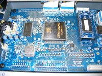
Here's a photo of the upper-most driver board, it is directly under the centerally located drive mechanism. Both stacked boards are in their own separate steel box, along with the drive mechanism. The SACD chip is located onthe lower board, along with the 33 mhz clock. As you can see, the 27mhz clock is on this particular board. Under the shanling heat sink, is a DVD video chip of some sort. You can see the lable on the bottom right corner, if you can read upside down. 😀
I'm going to have to go in there,and clean up the entire PS all around those driver boards, simply to get the best as is possible from the compromised design of the unit. I've no idea who's is better though: I find it not good to unessessarily pick on Shanling, who knows how the rest of these units (SACD Players in general) are designed and executed. Luckily, I have about 30 values/voltages of SP series OS-CON's lying about....
Here's a photo of the upper-most driver board, it is directly under the centerally located drive mechanism. Both stacked boards are in their own separate steel box, along with the drive mechanism. The SACD chip is located onthe lower board, along with the 33 mhz clock. As you can see, the 27mhz clock is on this particular board. Under the shanling heat sink, is a DVD video chip of some sort. You can see the lable on the bottom right corner, if you can read upside down. 😀
Attachments
SS ouput boards, before the tube output section
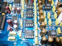
Here's a fairly clean image of the stock form of the SS/DAC output boards. Overall. it's very nicely done. As ususal these days the darned traces are VERY fragile. So constant part swaps are a big no-no. Find the right replacement part, change it out once, and leave it alone. I was very scared when I pulled the xo's. I was very lucky in that the boards (drive/xo boards) remained undamaged.
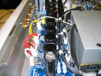
They are directly beside the drive mech's steel box. In the image of the drive mech boards, you can see the ribbon cables coming off the top of the image. Those two ribbon cables are connected directly to the O/P-(pre-SS)driver/DAC board, which the connection points are just out of sight on the left of the supplied image.
The digital volume control (TI/BB's latest digital volume chip) is to the right in this image, and there is decent 'look' to the board. If you follow the tech manual for the PCM1738..you will find that this is likely to be an exact duplicate of the suggested 'design' for utilizing the PCM1738, as suggested by TI/BB- as far as I/V and output section goes. Actually, it is....identical.
Nicely done, but overall..not very inventive. It works, and it would be harder to create a better layout, unless you wanted to use borbley's discrete amps instead. But.. you might as well design your own SACD/CD player at that point. There is enough room to put items above and below the boards, so modding is almost a 'dream'. The boards are all on metal brass stand offs. All boards.
I always find it amazing or ..depressing when I open up a high priced item and find the exact copy of the implementation instructions (tech manual copied layout) for a given chip or series of chips. I feel a monkey can do that, these days, with all the board layout software. Hell, I could do a better job!!! Doesn't anyone actually think about these things anymore? Where did all the real audio designers go???? Or were there never actually any, and I'm only coming to realize that now?
Edit: I will clarify that I do know there are some exceptional 'real' designers out there. These days, most/many companies seem to rely on spec type jobs, with little or no true inventivness.
It is all the other aspects of making/creating/running a company that makes such efforts exceptional. Any moneky can design these days. Keeping a company viable, or actually getting a product to a market, in an effective fashion ---now THAT'S the real challenge.
Here's a fairly clean image of the stock form of the SS/DAC output boards. Overall. it's very nicely done. As ususal these days the darned traces are VERY fragile. So constant part swaps are a big no-no. Find the right replacement part, change it out once, and leave it alone. I was very scared when I pulled the xo's. I was very lucky in that the boards (drive/xo boards) remained undamaged.
They are directly beside the drive mech's steel box. In the image of the drive mech boards, you can see the ribbon cables coming off the top of the image. Those two ribbon cables are connected directly to the O/P-(pre-SS)driver/DAC board, which the connection points are just out of sight on the left of the supplied image.
The digital volume control (TI/BB's latest digital volume chip) is to the right in this image, and there is decent 'look' to the board. If you follow the tech manual for the PCM1738..you will find that this is likely to be an exact duplicate of the suggested 'design' for utilizing the PCM1738, as suggested by TI/BB- as far as I/V and output section goes. Actually, it is....identical.
Nicely done, but overall..not very inventive. It works, and it would be harder to create a better layout, unless you wanted to use borbley's discrete amps instead. But.. you might as well design your own SACD/CD player at that point. There is enough room to put items above and below the boards, so modding is almost a 'dream'. The boards are all on metal brass stand offs. All boards.
I always find it amazing or ..depressing when I open up a high priced item and find the exact copy of the implementation instructions (tech manual copied layout) for a given chip or series of chips. I feel a monkey can do that, these days, with all the board layout software. Hell, I could do a better job!!! Doesn't anyone actually think about these things anymore? Where did all the real audio designers go???? Or were there never actually any, and I'm only coming to realize that now?
Edit: I will clarify that I do know there are some exceptional 'real' designers out there. These days, most/many companies seem to rely on spec type jobs, with little or no true inventivness.
It is all the other aspects of making/creating/running a company that makes such efforts exceptional. Any moneky can design these days. Keeping a company viable, or actually getting a product to a market, in an effective fashion ---now THAT'S the real challenge.
Attachments
Re: SS ouput boards, before the tube output section
I always get horrified about the way manufacturers (including "high-end") use op-amps.
There's a lot to improve on the PSU layout of the op-amps there.
Welcome to reality.
Did you think you had something original in your hands?😱
No, most gear is datasheet or appnote implementation, most of the times with a horrible PCB layout.
I've opened too many gear over the years and nothing shocks me anymore.
Original is getting the pre-outs from the outputs of the power amp (speaker-level), attenuated and buffered with a single transistor. 😱
This is how Yamaha makes it on some AV receivers.
So why are you shocked?
KBK said:Nicely done, but overall..not very inventive. It works, and it would be harder to create a better layout...
I always get horrified about the way manufacturers (including "high-end") use op-amps.
There's a lot to improve on the PSU layout of the op-amps there.
KBK said:I always find it amazing or ..depressing when I open up a high priced item and find the exact copy of the implementation instructions (tech manual copied layout) for a given chip or series of chips. I feel a monkey can do that, these days, with all the board layout software.
Welcome to reality.
Did you think you had something original in your hands?😱
No, most gear is datasheet or appnote implementation, most of the times with a horrible PCB layout.
I've opened too many gear over the years and nothing shocks me anymore.
Original is getting the pre-outs from the outputs of the power amp (speaker-level), attenuated and buffered with a single transistor. 😱
This is how Yamaha makes it on some AV receivers.
So why are you shocked?
Way back in '87 or so.........
When I worked on my first CDP (a "Maggot Box" CDB-472), I was horrified at how poorly the PCB was laid out. Especially wrt ground. Ground was ground, except when it was easier to run the bypass cap to some other rail that had its own supply. The noise, hum, ripple, and plain ol' **** on the rails was easily seen on the most rudimentary of test equipment.
My initial thought was that I would fire the junior engineer that did it if he worked for me. Then it hit me.............no engineer did it..........an autorouter did it.
Sure, with skill, they could have manually routed the critical analogue ground returns. Draw your own conclusion(s).
Jocko
Once upon a time, on a Sony SCD-XA333ES, I removed the crystal oscillator, which had bent legs and was standing on the air at almost 1cm from the PCB.
Just by cutting the legs and soldering it ON the PCB, the sound clearly improved.
Of course, that total piece of junk begged for a good clock and it received it later.
But it's curious to see how Sony mounts the oscillators on some players.
Like a cap with bent legs, standing in the air.
Just by cutting the legs and soldering it ON the PCB, the sound clearly improved.
Of course, that total piece of junk begged for a good clock and it received it later.
But it's curious to see how Sony mounts the oscillators on some players.
Like a cap with bent legs, standing in the air.
Lars Clausen said:With a few exceptions, the same would be the case in any SACD player. That's why we always recommend a CD player to play CD's. The PLL circuit in almost every SACD player will always be the reason it is inferior to a CD player, contradictionary to what the colorful adds from the SACD companies want you to think.
But think back a few years. Then it was DVD players: A DVD player can play CD's with MUCH higher definition than a CD Player! A DVD player, the only player you need.
Was it true???? 😎
My suggestion is: Get a good CD player instead!
DUDE ! you mean to tell me that selling my CD player for SACD player was NOT a good idea ? 😡Madmike2 said:
For 2-channel CD playback, no.😀
And SACD may not last much longer...🙄
Re: Re: SS ouput boards, before the tube output section
I'm not shocked, I just tend to say things with much emphasis. 🙂
I bought this unit largely...sight unseen. So far, I'm well pleased with the purchase, just for the sheer fun of having something around to mess with when I get itchy.
I'm used to being able to take apart everything I purchase, before I actually purchase it. I used to have a good enough rapport to do that with a few shops. Those were the days.
One way to get to the best out of this shanling chassis is that it needs hard wired custom wiring harnesses. That's a long and thankless job, but it will benifit tremendously. When I do that, I test fit the cables for access if repair is needed. I find the extra length is negligible in effect, and actually aids in layout at times.
I love audio shows. It's nice to find platforms of interest to fool around with. One quick way to actualize experiments, is to find a suitable platform pre-made by someone else. 😉
carlosfm said:
Welcome to reality.
Did you think you had something original in your hands?😱
So why are you shocked?
I'm not shocked, I just tend to say things with much emphasis. 🙂
I bought this unit largely...sight unseen. So far, I'm well pleased with the purchase, just for the sheer fun of having something around to mess with when I get itchy.
I'm used to being able to take apart everything I purchase, before I actually purchase it. I used to have a good enough rapport to do that with a few shops. Those were the days.
One way to get to the best out of this shanling chassis is that it needs hard wired custom wiring harnesses. That's a long and thankless job, but it will benifit tremendously. When I do that, I test fit the cables for access if repair is needed. I find the extra length is negligible in effect, and actually aids in layout at times.
I love audio shows. It's nice to find platforms of interest to fool around with. One quick way to actualize experiments, is to find a suitable platform pre-made by someone else. 😉
Attachments
Jocko: So right! Sometimes you wonder how these office boys got through tech college .... 🙄
About the jitter model measuring circuit, it seems you had the same idea as me, with this circuit. How sensitive could you go?
I bet with the simple and cheap circuit from the oliveaudio site you can measure at least a 10 dB difference in jitter between a KWAK and a Guido Clock. (Just to let my own stuff out of this discussion).
And no ..... i will not tell you guys which one is better ... 😀
Lars Clausen said:I bet with the simple and cheap circuit from the oliveaudio site you can measure at least a 10 dB difference in jitter between a KWAK and a Guido Clock. (Just to let my own stuff out of this discussion).
And no ..... i will not tell you guys which one is better ... 😀
I suppose that in each case you are using the recommended PSUs?
Did you measure the Tent clock with Guido's choke PSU?
Also, do you have a solution like the Tent XO3, with SPDIF reclocking and output?
I don't think so...
I do not know how sensitive that I can go. Wenzel has the same basic circuit on their site. I suspect that they have some low-noise amps in theirs. I do know that I can easily see the difference between a decent clock and the bog standard one in a CDP.
The 2 bugs in my set-up are repeatability, wrt getting the exact same numbers each and every day. Also, some mains lines harmonics show up in the measurements.
I wonder about oliveaudio site one. All he is really doing is dividing the UUT, making the output lower in frequency. The lower it is.........how does his op-amp like that? I do not think that it has enough filtering before the op-amp. Plus, how does the op-amp like seeing an input that close to the rails???
Jocko
Good point Jocko! Maybe the rails for the op-amp should be higher than the rest. Or use a low voltage high speed opamp.
Thanks for the hint 🙂
Carlosfm: No need to take offense, i am not saying any of the two clocks are bad, just that the measurement suggested is sensitive enough to distinguish between these two fine clocks. 😉
Thanks for the hint 🙂
Carlosfm: No need to take offense, i am not saying any of the two clocks are bad, just that the measurement suggested is sensitive enough to distinguish between these two fine clocks. 😉
Lars Clausen said:Carlosfm: No need to take offense, i am not saying any of the two clocks are bad, just that the measurement suggested is sensitive enough to distinguish between these two fine clocks. 😉
No offense at all, I was just asking because it would be nice to know the conditions of the test.
Carlosfm: I am confident it will not make much of a difference for the jitter measurement. Or model of jitter measurement, to be more precise. That's not to say it will not make a difference for the sound. Many many cases have shown that measurements don't correllate with sound differences. But that's another story 😉 Anyway .. Carlos .. why don´t you make the simple test, and post the result here. 😉
At best, the OliveAudio circuit shows the phase noise of the UUT as modulated by the phase noise of the 74AC74 flipflop, which is considerable. In addition to their legendary noise, most AC logic doesn’t have balanced propagation delays. A “perfect” oscillator will show significant phase noise, as measured by the OliveAudio circuit, while a “less than perfect” oscillator may show less.
Ulas: Only providing that the phase noise of the 'imperfect oscillator' is in counterphase with that of the 74AC74.
Which it is not, so .....
On contrary to what you claim above the jitter noise of the AC74 (and HC74) was found to be relatively low. (In actual measurements).
Further i had this circuit give output results correlating nicely with jitter specs of different high speed voltage comparators. So personally i find the simple circuit trustworthy. And i also think it's great that it gives anybody the opportunity to evaluate the true quality (not just the loose claims) of different clock providers, including my self 😀
- Status
- Not open for further replies.
- Home
- Source & Line
- Digital Source
- Clock wars?: 'Superclock 3' vs. KBK's personal design