Coulda woulda...
Im irritated noone knows a reply to the amp question.
Called engineer today. Said yes yes yes to all questions above.
Maybe voltage divider for very high output only, depends.
Im irritated noone knows a reply to the amp question.
Called engineer today. Said yes yes yes to all questions above.
Maybe voltage divider for very high output only, depends.
OK. Confusion.
Im measuring TSP of my electrostatic here, with 3.75 then 1 then 0.1 volt, all are different
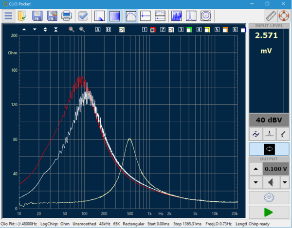
Which one is correct? 🙂
Then I also measured a standard 8" driver.
Most values are OK except of the Qes & Qts.
Clio measures 0.35 / 0.34
But the driver was measured by a magazine with MLSSA & highend equipment as 0.21 / 0.2 .....
Is the calibration and the cables and the alligators precise enough?
Isnt the 1.4 seconds logchip way too short?
Is the device-output apropriate (low level & high resistance) ??
cheers
Josh
Im measuring TSP of my electrostatic here, with 3.75 then 1 then 0.1 volt, all are different
Which one is correct? 🙂
Then I also measured a standard 8" driver.
Most values are OK except of the Qes & Qts.
Clio measures 0.35 / 0.34
But the driver was measured by a magazine with MLSSA & highend equipment as 0.21 / 0.2 .....
Is the calibration and the cables and the alligators precise enough?
Isnt the 1.4 seconds logchip way too short?
Is the device-output apropriate (low level & high resistance) ??
cheers
Josh
1st, what I see in your picture -> output 0.1 V and input range 40 dBV is not the best option
You have to ensure manually that the input level is in a "green" range, try -10, -20dBV or lower ..
And yes Clio Pocket is precise enough, I compare it to other Systems - with the same driver I get the same results.
But this are often different to provided values from magaziens or manufacturer ...
You have to ensure manually that the input level is in a "green" range, try -10, -20dBV or lower ..
And yes Clio Pocket is precise enough, I compare it to other Systems - with the same driver I get the same results.
But this are often different to provided values from magaziens or manufacturer ...
Hi Dirk
Nope. +40 means it can receive higher level without clipping. if I go down to 0 on the input (keeping same output) it will clip. Also confused me, this way of seeing the value the other way around 🙂
So using one and the same output voltage with different input sensitivity, doesnt change a thing. As long as it doesnt clip, of course. But lowering the level on the input gives exactly the same curve.
Just the output level is making it completely different!
In order to prevent the clipping while always trying to be on the upper green input level for good SNR i changed the sensitivity once, and once different output levels same input.
I dont get other results though. The TSP / Impedance measurement varies DRAMATICALLY depending on the output voltage i set.
This doesnt make sense at all! This way its kinda "pick what u like". Values should be absolute! Does anyone know help here? Otherwise ill throw this box to the bin!
cheers
Josh
Sorry, but you are wrong.
T/S parameters indeed vary with different measuring voltages. How can they be absolute?
T/S parameters indeed vary with different measuring voltages. How can they be absolute?
Ok then whats the norm for TSP values everyone measures??
1? 2.83?
More funny that the manual kind of sais “ pick 1v for start and increase or whatever “.... ??
If my 8” driver should have Qts 0.25 but measures 0.35 here im getting curious...
1? 2.83?
More funny that the manual kind of sais “ pick 1v for start and increase or whatever “.... ??
If my 8” driver should have Qts 0.25 but measures 0.35 here im getting curious...
2.83V@8 ohms is the normal value for driver testing, exactly 1 watt. Now if your using a 4 ohm driver you need to adjust the voltage so you are also measuring at 1 watt amplifier output. The real problem with this absolute voltage value is that it doesn't take into consideration the true impedance of the speaker, but it is the accepted norm in the industry.
I've seen levels from 0.3V ... 1V suggested in books/web, but generally not the full 2.83V as for acoustic response. The T/S model is for a "small signal behaviour" so one should measure that at relative low level. yet the signal to noise needs to be high enough to avoid the noise on the resulting graph.
SB suggests a 1V at Fs here
http://www.sbacoustics.com/index.php/download_file/-/view/191/
Anyhow - it is a good idea to take all of the measured parameters and enter them into any of the box simulator of choice. Preferably one where you can overlay another simulation on top. As the T/S parameters are interlinked it can easily be that your seemingly quite different numbers will result in a very close acoustic response model. So there is no need to obsess getting each number same as datasheet.
Always have a 10 Ohm precision resistor at hand so as, in case of doubt, you can check the calibration with the alligators within a few secondsIs the calibration and the cables and the alligators precise enough?
Great replies to Josh's question from everyone. 🙂
I thought about replying, but realized that it's just something that has to be seen to understand, thus a new video:
CLIO Pocket Impedance Measurement - Linearity
I thought about replying, but realized that it's just something that has to be seen to understand, thus a new video:
CLIO Pocket Impedance Measurement - Linearity
I've seen levels from 0.3V ... 1V suggested in books/web, but generally not the full 2.83V as for acoustic response. The T/S model is for a "small signal behaviour" so one should measure that at relative low level. yet the signal to noise needs to be high enough to avoid the noise on the resulting graph.
SB suggests a 1V at Fs here
http://www.sbacoustics.com/index.php/download_file/-/view/191/
Anyhow - it is a good idea to take all of the measured parameters and enter them into any of the box simulator of choice. Preferably one where you can overlay another simulation on top. As the T/S parameters are interlinked it can easily be that your seemingly quite different numbers will result in a very close acoustic response model. So there is no need to obsess getting each number same as datasheet.
This method is the best and can be standardized and repeated. I also use it.
Thank you Langston! The visual instructions how to recognize & finetune helped a lot!!
Finally i get perfect result like in the magazine:

Finally i get perfect result like in the magazine:
Langston - or anyone who knows - , one more question 🙂
The calibration of the frequency response of clio pocket interface...
is it only a loopback calibration, or are out- and in-put linearized individually???
Important to know when I want to measure external AD or DA converter 🙂
The calibration of the frequency response of clio pocket interface...
is it only a loopback calibration, or are out- and in-put linearized individually???
Important to know when I want to measure external AD or DA converter 🙂
The calibration of the frequency response of clio pocket interface...
is it only a loopback calibration, or are out- and in-put linearized individually???
Good question, I have no idea. 🙂
When placing a high quality, high impedance voltmeter on the output after calibration I get the same 1kHz reading that CLIO Pocket and CLIO 12 report in their multimeters (F4).
Whichever method the Italians employ, it works well.
As a side note, if you don't have a high quality calibrated multimeter you should consider buying one. Like a good oscilloscope, it's just one of those things that is more important than food, shelter or clothing. 🙂
Important to know when I want to measure external AD or DA converter 🙂
from my point of view, it could only be a loopback calibration.
For individual linearization of in- / out- put you need extrenal reference equipment ...
Clio ( Pocket and FW ) used an internal voltage reference circuit for calibration of output level.
Important to know when I want to measure external AD or DA converter 🙂
with Clio Pocket you could not measure a AD or DA converter, it works only on analog level...
Regards Dirk
with Clio Pocket you could not measure a AD or DA converter, it works only on analog level...
Very true Dirk, but as a side note the QC version of CLIO 11 and 12 can use any sound device connected to the computer it's running on as an output or input (but not both at the same time).
For example; if a D/A converter were connected to the computer CLIO QC was running on, CLIO could route the output of any of its measurement routines through the D/A and back into the CLIO audio interface.
The reverse is true as well; the analog output of CLIO's audio interface box can be connected to the input of an A/D that is attached to the computer and CLIO can select that A/D for its input.
With Dante Via, this means CLIO QC can also measure devices on a Dante network.
Finally, either CLIO Std or QC can use the SPDIF output on the rear panel of its audio interface box to feed devices with digital inputs (48kHz, 96kHz or 192kHz). This is a single RCA connector, but if optical TOSLINK is required, a simple and inexpensive converter box can be used for lossless conversion.
Here's a look at CLIO QC's options where other sound devices can be selected:

Last edited:
Hi Langston,
Thanks for the info regarding QC version.
I only know / own the STND version of Clio 11, it's much enough for DIY hobby ... 🙂
Also a note from my side, it seems that Audiomatica has now increase the price with release of "Clio 12 - USB Hardware".
In Europe it's now ~ 500 € more expensive than "Clio 11 - FW Hardware" 🙁
Regrads
Dirk
- Home
- Design & Build
- Equipment & Tools
- CLIO Pocket