Hello,
I have never seen the English translation so i dont know if they are good. Usually you need a real person to write something sensible
My friends Hiraga uses Tent shunts for the input stage. Very similar to the ones used by people to modify the DDDAC before they were integrated into the circuit during an update.
Better spec parts will not give you automatically a better amp. If so there wouldn't be that much garbage available.
My friend changed his nearly 30 year old caps by new ones. Guess what the old ones sounded better. The old ones were real professional caps used by serious companies like Dassault . They are still available but not that easily.
I don't have any doubt about the competence of the dddac designer.
Even with not so big caps the rectifier and transformer will suffer a lot. I have had it explained by a real French audio technician. Even with a CRC or CLC you can make the first cap to big. Making the transformer bigger sometimes also worsens the problem.
Which chokes did you use as input choke for your tube gear?
All the people who redesigned the original Hiraga so it will have a bit more power will say it blew away the old one. There might be kits available on the internet that will be ok compared to complete devices available in a real shop but most of them sound just bad.
Greetings Eduard
.
For an C1 Lr R C2 power supply filter , I've shown the transfer function ,
and how to calculate the value of the dampening resistor , in post #134 on page 7 .
Total dampening R = 2 * Zeta * sqrt ( L / C2 )
......................... where Zeta = 0.707 in an ideally dampened system
Also , looking from the supply rail into the amp , the supply rail sees a CCS ( Constant Current Source ) ,
which has a very high impedance . So the Amp itself does not provide any dampening .
and fo = 1 / ( 2 * Pi * sqrt ( L * C2 ))
However , after building this , and conducting listening tests with FAB's USSA 3.2 Amp ,
my advise is to help dampen the system by making C2 very large and leave the dampening resistor out .
Also , if C2 so large , then fo will be subsonic anyway .
Attachments
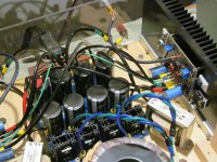
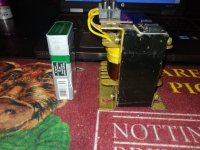
To explain FAB's USSA 3 and 3.2 Amps .
FAB has taken the F5 , removed the IRFP240 , and replaced with a MOSFET driving an Exicon Lateral ECW20n20 .
The transconducance of the ECW20n20 is low , hence the need for the driver MOSFET .
Because the ECW20n20 are lateral MOSFET's , the source resistors are 0R01
and are used to be able to measure output bias current .
Same story with the IRFP9240 .
Note how the star ground node is on the power supply board , and that the USSA board has 2 analog ground connections .
One ground for the low current signal transistors 2sk170's and 2sj74's .
The other analog ground for the high current MOSFET's - which are biased at 1.2 Amps .
.
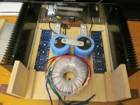
The transformer I used was 600VA and the supply caps are 22,000uF each .
.
Not shown in the photo is a Fo Felix DIY EMI filter - which I highly recommend .
.
... and its one of the best Amps I'be ever heard .
FAB has taken the F5 , removed the IRFP240 , and replaced with a MOSFET driving an Exicon Lateral ECW20n20 .
The transconducance of the ECW20n20 is low , hence the need for the driver MOSFET .
Because the ECW20n20 are lateral MOSFET's , the source resistors are 0R01
and are used to be able to measure output bias current .
Same story with the IRFP9240 .
Note how the star ground node is on the power supply board , and that the USSA board has 2 analog ground connections .
One ground for the low current signal transistors 2sk170's and 2sj74's .
The other analog ground for the high current MOSFET's - which are biased at 1.2 Amps .
.
The transformer I used was 600VA and the supply caps are 22,000uF each .
.
Not shown in the photo is a Fo Felix DIY EMI filter - which I highly recommend .
.
... and its one of the best Amps I'be ever heard .
Last edited:

Andynor ,
With the 2.5mH Chokes in , I connected a damping resistors of 0.25 ohms , the power supply I used was fine for 1 channel ,
but sounded awful with both the L and R channels .
I took out the chokes and dampening resistors , and replaced them with 0R1 12 Watt
and couldn't hear any difference when the power supply was driving 1 or 2 channels .
Then put the chokes back in without a dampening resistors , and the L and R channels sounded amazing .
For a test CD , a piano concerto separates the sheep from the goats real fast .
Mozart Piano Concerto No. 20 , with Lief Oves Andsnes ( aka the Vikings Play Mozart ) .
https://leifoveandsnes.com/project/mozart-piano-concertos-nos-17-20/
The orchestral strings are the best I've ever heard - nearly all the usual harshness is gone .
Another great test CD is Dave Brubeck's Time Out .
If I have the values correct from your C1 Lr C2 power supply on post #119
Hammond 159ZJ choke , L = 10mH and r = 0.16 ohms
C2 = 300,000 uF / 4 = 75,000uF
So the fo = 1 / ( 2 * Pi * sqrt ( L * C2 ) ) = 5.8 Hz
without a dampening resistor Zeta = r / 2 * sqrt ( C2 / L ) = 0.22
Math , circuit simulation , and measurements provide a great guide for design .
But ultimately , we listen to Amplifiers .
So my revised recommendation, with your power supply , fo = 5.8 Hz , so now I'd say leave the dampening resistors out .
.
Yeah, in the ned, a listening test is a must due to the unknowns (to simulation/calculation) related to interconnecting wiring variations. Also, we are highly emotional individuals who praise individuality. Simulations can't cope with that 🙂Then put the chokes back in without a dampening resistors , and the L and R channels sounded amazing .
Was that with a 2.5 mH choke or a 10 mH choke?
What is this dampening resistor you talk about? How is it connected?
Yes , the math , circuit simulation and measurements point us in the right direction ,
but ultimately we listen to audio amplifiers .
I used Hammond 159ZL chokes , where L = 2.5 mH and r = 0.044
with C2 = 44,000uF , originally I connected a 0R25 dampening resistor in series with the choke .
Andynor used Hammond 159ZJ chokes , where L = 10 mH and r = 0.16 ohms
with C2 = 75,000uF .
But in both cases , fo is below 20Hz , so from listening , I'd say leave the dampening resistors out .
The first bank of caps does the heavy lifting ( C1 ) , and has to cope with most of the ripple current .
If the second bank of caps are increased ( C2 ) , then the sonics becomes more natural and more forward .
But I'm not sure if the sonic improvement is from the ability to store more charge , or from a lowering of the ESR .
Look inside a Pass Labs Amp , and there are quite a number of power supply caps .
.
The FirstWatt amps do not use local power supply rails' decoupling (on AMP PCBs), which was always a puzzling element. Nelson probably knows why... I do have a theory, but I will refrain from speculating.
Chokes can compensate nicely, but introducing local power supply rails' decoupling (on AMP PCBs) will also work with amazing results... Chokes will prevent; decoupling caps will cure. However, chokes will also affect the sound dynamics that might be too much for some. I think 2.5 mH is a perfect value as it provides the best benefit vs. trade-off.
Chokes can compensate nicely, but introducing local power supply rails' decoupling (on AMP PCBs) will also work with amazing results... Chokes will prevent; decoupling caps will cure. However, chokes will also affect the sound dynamics that might be too much for some. I think 2.5 mH is a perfect value as it provides the best benefit vs. trade-off.
Yes , the Belles 150a reference power amp I have has the power supply caps right on the amp board itself .
Notice on the USSA 3.2 amp shown above , I used 12 awg and 10 awg cable for the power wiring .
Here is a power supply idea I was thinking of .
But its all about getting current to the load .
From listening , the bigger the power supply , the more the sonics move forward and the sound becomes more natural .
.
Notice on the USSA 3.2 amp shown above , I used 12 awg and 10 awg cable for the power wiring .
Here is a power supply idea I was thinking of .
- 600VA AnTek transformer
- diodes de jour
- 2 computer grade electrolytic caps take the brunt of the ripple ( the ESR on some of these is in the neighbourhood of 4 mOhms ) .
- Hammond 159ZL chokes
- Then the L and R channel get their own bank of power supply caps .
- Consider using Belden 19364 for the internal hydro wiring because its got a foil shield
But its all about getting current to the load .
From listening , the bigger the power supply , the more the sonics move forward and the sound becomes more natural .
.
Attachments
Last edited:
Very interesting and informative, @Uunderhill! And great to hear about your good results
It would also be interesting to do a listening comparison between decoupling (Bokys suggestion) and CLC.
To detail the specs of my PSU in full, C1 is 47kuF. C2 is 147kuF per rail per channel (47+100k). Overkill was the goal, understood as making it big enough and then some. It does seem a very low Fs was achieved
Probably there is some negative effect of this setup too, buy I am pretty happy so far.
The FirstWatt amps do not use local power supply rails' decoupling (on AMP PCBs), which was always a puzzling element.
Yes . Building an F5 Amp , it would be tempting to drill holes in the boards , 10 mm apart , to add 2 local reservoir caps .
Squeeze in two 6,800uF caps with snap in leads on the boards ( between + Ve and Gnd and - Ve and Gnd ).
Looking it up , for a 18 cm length of 12 awg cable , the inductance is in the neighbourhood of 180nH .
I have no idea if this makes any difference in in the audio bandwidth at 1.2 Amps .
However , with 1.2 Amps flowing though this length , I'm measuring a voltage drop of 2.6 mVdc .
Which gives R = 2.2 m Ohms , which may not seem like much , but then the ESR of the power supply caps
is in the neighbourhood of 9 to 22 m Ohms .
.
" Overkill was the goal, understood as making it big enough and then some. "
When FAB designed a variation on one his Amps , he used dual CRC power supplies , with 4 x 47,000uF per board .
So with 2 boards , that's a total of 376,000 uF .
From listening , the bigger the power supply , the more the sonics sound more natural and more forward .
.
Also , I highly recommend adding a Fo Felix DIY EMI filter .
It was designed specifically for audio equipment , so it does not have a cap between the hot and earth ,
and the neutral and earth .
For the common mode choke , I used a Bourns 8120 RC , but it will probably need potting .
https://www.bourns.com/docs/Product-Datasheets/8100_series.pdf
.
When FAB designed a variation on one his Amps , he used dual CRC power supplies , with 4 x 47,000uF per board .
So with 2 boards , that's a total of 376,000 uF .
From listening , the bigger the power supply , the more the sonics sound more natural and more forward .
.
Also , I highly recommend adding a Fo Felix DIY EMI filter .
It was designed specifically for audio equipment , so it does not have a cap between the hot and earth ,
and the neutral and earth .
For the common mode choke , I used a Bourns 8120 RC , but it will probably need potting .
https://www.bourns.com/docs/Product-Datasheets/8100_series.pdf
Hey everybody!
So over the years people have asked about the old version, made by someone else.
It's probably time for an updated one. This one is a bit different. You may notice it does not have following capacitors after the choke. I have tried both ways, and my preference is strongly without the following X2 capacitors. Also the capacitors prior to the choke are not varied in size because overall capacitance is more important - and they won't randomly resonate with each other.
The other major change is the addition of bypass resistors for the chokes. These don't ruin the...
- Destroyer OS
- Replies: 220
- Forum: Group Buys
is a 25mH choke overkill?
I'm no expert , but in a power amp supply , I've never seen a value this large .
When current flows through an inductor , a magnetic field is created . That magnetic field then opposes any changes in the current .
So an inductor or choke acts like a current fly wheel .... it tries to maintain a steady current .
If the inductor or choke is too large , when there are sudden current demands , a choke that is too large is going to starve the Amp of current .
Possibly the easiest way to actually test if the 25mH choke is too large is with simulation software .
Set up a C Lr C filter
Introduce a load with a sudden current demand ( step function ) - and watch if the voltage rail sags .
But again , I've never seen a choke this large used a power amp supply .
.
The voltage drop on current increase depends mostly on its DC resistance. A low DC resistance choke is big, heavy, and expensive, though.
- Home
- Amplifiers
- Pass Labs
- CLC vs. CRC