Please indulge an Ultimate Greenhorn. For a single stereo amp, the following would be required correct?
1 pair amp PCBs (duh)
2 Rectifier Snubber PCBs
1 CL60 / AC cap board
1 PSU board - how does this differ from the store PSU board? How is the V8 board different?
Which mosfets are considered "better"?
Thanks in advance 🙂
For a stereo Aleph 30...
1 pair amp PCB's.
2 Rectifier Snubbers
1 "New Original" F5 PSU. (no need for CL-60/AC Cap board, that function is integrated on the "New Original"
The "New Original" board is different from the store board in that it has the AC cap/CL-60's on board, and the caps after the resistors in the CRC filter bank split off for each channel. Not dual mono/monoblock, but not a single CRC. Somewhere in between.
The "New original" vs. V8. V8 has an additional RC stage, but no decoupling between channels. You get a little more filtering with the V8, but at the price of a slight voltage drop on the additional RC stage.
For MOSFETs, 2SJ313's are the top shelf option in Q1&Q2, but they're obsolete. If you can get matched pairs, go for it. The normal IRF9610's are very good.
Perfect, thank you. One last question, how closely do SJ313s have to be matched? I have several but not sure if they're close enough. Also, do they only need to be matched to each other or to the SK2013s as well?
The mosfets in the differential pair (Q1, Q2) need to be matched within 10% or so. (3P20, 9610, J313, etc…)
The constant current source (Q3) does not need to be matched to anything.
There are no TO-220 N mosfets (K2013, 610, 3N30, etc…) in this amp.
The constant current source (Q3) does not need to be matched to anything.
There are no TO-220 N mosfets (K2013, 610, 3N30, etc…) in this amp.
Last edited:
The mosfets in the differential pair (Q1, Q2) need to be matched within 10% or so. (3P20, 9610, J313, etc…)
The constant current source (Q3) does not need to be matched to anything.
There are no TO-220 N mosfets (K2013, 610, 3N30, etc…) in this amp.
Jim - excellent point.
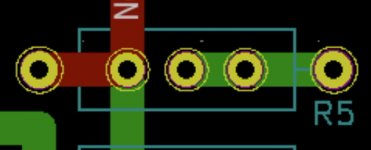
Upon 2nd thought, I have moved the MOSFET back to right angles. I fear some metal tab 9610's will be shorted out when back to back.
Builder needs to ensure electrical isolation but the goal is to be able to tie them together for thermal tracking.
Or don’t worry about it much, it’s not as important as people think…
There is "people" and there is ZM (link)

Honestly I never bothered to try on my A30 but if it comes at no cost, I would certainly implement it.
A back-to-back arrangement could probably help also in case of other TO-92 package fets like ZVP3310 for spreading the heat between the pair (link)
I am still doing my homework but this ZM guy spammed all Alephs threads
 One more example is to bypass a 220uF electrolytic with a 100nF MKC cap (link) that I believe is C10 in the schematic in the first post (slow learner 😱).
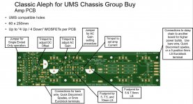
What are the dimensions of the PCB? It appears to be longer than 250 mm so how would a pair of these fit on each side of a 5U 500mm chassis?
What are the dimensions of the PCB? It appears to be longer than 250 mm so how would a pair of these fit on each side of a 5U 500mm chassis?
Attachments
Randy, did you consider paralleling your pot footprints with resistor footprints?. That could give some the opportunity to ‘set and forget.’ And I’m thinking specifically about the AC gain pot, but I suppose other pots could benefit too. Just an idea, certainly no pressure to make the update.
Maybe not the same idea, but…
I put a little mark on the board where one can jump the pot and just use the default resistor value from the pass schematic. I’m planning to write that up in build notes. Example, use 392R and jump the offset pot, or use different resistor and pot.
I jumped 2 of 3 pots on my aleph 60 mono test build using some clipped resistor leads. Easy peasy.
Side note - I’m planning to pick values in the BOMs with pot at ~50% value (factory default) + resistor = ~original schematic value. This way if someone forgets to measure and just puts the pot in its “close enough” to start.
So an Aleph 60 would require 2 heat sinks per channel? Would 4U 300mm heat sinks be large enough?
I think it would be reasonable. Will run pretty toasty though, so keep good room under and above the chassis.
Would the 5U 500 work for the alpha 60 as a stereo amp? I think it will, but want to check first.
- Home
- Amplifiers
- Pass Labs
- Classic Aleph Amplifier for Modern UMS Chassis