I did correct that already Pafi but did post the previous picture sorry, it did still not work.
Multisim is kwown for bad models.
Hi Pafi
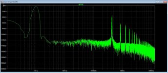
Thanks for the info, I have did some tests to see what happens, see the pictures.
TNT you did ask Pafi? because I did not see these peaks on sim, but did use a HD shaper as was on papers, did try some different things to learn and see, class D is not such playtool als liniair amps, she are quite complicated, also in pcb design.
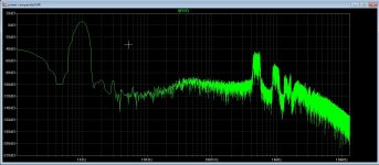
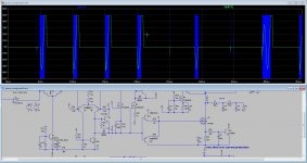
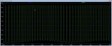
See on plot that the carrier is on 1.5 Mhz, but when I come close to rails it drops to 700 khz. this is to high and bad for EMI.
regards
What is the switching frequency.. This is probably according to Oersted DTU paper, and switching frequency is quite high, probably 800 khz?
why dont you use spice FFT function instead of fourier FFT graph ?
FFT function gives numerical value of thd.
Later posts: Whats the point of NOT having LC filter under loop and using sigma delta modulation ? UCD type is always better
I think this is the best currently on forums UCD like (I will claim so after I test this for transients etc) http://www.diyaudio.com/forums/clas...ity-power-amplifier-2x100w-2.html#post4642756
Last edited:
What is the switching frequency.. This is probably according to Oersted DTU paper, and switching frequency is quite high, probably 800 khz?
why dont you use spice FFT function instead of fourier FFT graph ?
FFT function gives numerical value of thd.
Later posts: Whats the point of NOT having LC filter under loop and using sigma delta modulation ? UCD type is always better
I think this is the best currently on forums UCD like (I will claim so after I test this for transients etc) http://www.diyaudio.com/forums/clas...ity-power-amplifier-2x100w-2.html#post4642756
Trouble is I do not now excactly how to do that, LTspice is bigger then the small program let see, however the 64 bit version is crashing all the time.
If you can explane in some words how to do, because I only see the normal FFt function and use hanning.
Yes it is high I had also try 24dB bessel low pass for see what happens also, I did try the loop included but this did lower the osc frequenty very low because of fase shift, it is however possible to include a extra loop from coil like I did see on some ucd designs, this paper is very intersting..
https://www.hobbielektronika.hu/forum/getfile.php?id=253790
regards
Attachments


Last edited:
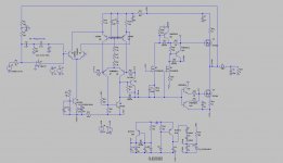
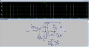
You mean this schematic, it has very low distortion and is a schematic mu poles implemented.
Was mine schematic a delta sigma? I have one who is to high switching and not usable, also delta sigma has small pulses, excuse me but class D is not a topic I have much experimence with but get interested because some smees to sound tube like with much detail, and yse this where ucd desigs who have more poles inserted, (resister caps).
This schematic can be implemented in mine discrete comparator, I can try what it does.
regards
Attachments
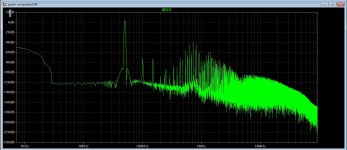
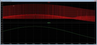
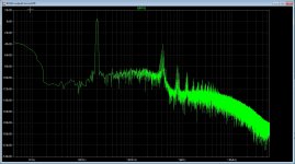
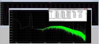
@Grizlek The carrier of these simulation was 450Khz and distortion when 1.2 amp in 8 ohms HD is minus 105 dB or 0.0005623 % or maybe even lower.
When 5 amp output it did -80 dB or 0.01 % but was in simulation not in real, I think I go try some day after the lineair circlotron is ready whith the fast opamps
we can make nice modulators..
Tests where with coil not in loop, maybe 24dB bessel do nice here, some papers are there somewhere about it.
regards
Attachments
Last edited:
Trouble is I do not now excactly how to do that, LTspice is bigger then the small program let see, however the 64 bit version is crashing all the time.
If you can explane in some words how to do, because I only see the normal FFt function and use hanning.
Yes it is high I had also try 24dB bessel low pass for see what happens also, I did try the loop included but this did lower the osc frequenty very low because of fase shift, it is however possible to include a extra loop from coil like I did see on some ucd designs, this paper is very intersting..
https://www.hobbielektronika.hu/forum/getfile.php?id=253790
regards
If your sine source for transient analysis is 1000 Hz then :
" .four 1000Hz 6 I(r6) "
"6" is number of harmonics.
Some of your schematics have pre filter feedback, not post filter feedback.
Yes this linked schematics is great, but you have to use integrator limiter, have not tried how it works, do not use output voltage peak over 50% Vcc.
For high modulations there is integrator limiter (which I do not know how it works havent simulated yet)
This linked schematics seems to be basically NCORE (one of the best ucd types class D)
Beter is to use "discrete comparator" and op amp instead descrete elemetns when you are testing feedback, later you can add your design
@Grizlek The carrier of these simulation was 450Khz and distortion when 1.2 amp in 8 ohms HD is minus 105 dB or 0.0005623 % or maybe even lower.
When 5 amp output it did -80 dB or 0.01 % but was in simulation not in real, I think I go try some day after the lineair circlotron is ready whith the fast opamps
we can make nice modulators..
Tests where with coil not in loop, maybe 24dB bessel do nice here, some papers are there somewhere about it.
regards
But this 0,0005623 % thd is pre filter feedback design, like in this schematics, right ?
But this 0,0005623 % thd is pre filter feedback design, like in this schematics, right ?
Yes filter output is not used, I did think about a bessel 24dB there, because these do sim nice and is never tryed as I do now, but have seen it on the internet ghowever can not find it anymore.
regards
Have done some more tests, like put in protection and dead time, (needs more tests) do work as a one shot protection, protection speaker is with a pcb and relay, not yet implemented, and needs to look at a soft limiter for protection when overdriven, not yet done, maybe with a extra opamp and diodes in feedback line, maybe some tips, thanks.
.
.
Attachments
-
 ScreenHunter_44 Mar. 08 21.43.jpg305.7 KB · Views: 88
 -
 ScreenHunter_46 Mar. 08 23.21.jpg325.9 KB · Views: 73
 -
 ScreenHunter_48 Mar. 09 13.28.jpg234 KB · Views: 114
 -
 ScreenHunter_49 Mar. 09 21.11.jpg292.4 KB · Views: 90
 -
 ScreenHunter_50 Mar. 09 21.15.jpg302.1 KB · Views: 83
 -
 ScreenHunter_53 Mar. 10 13.05.jpg179 KB · Views: 138
I have play with a IR chip for class D, however I see the negative side is not complete closed, and sticks with -70 volts while the top do fine and go to 90 volts, I get dissipation on that lower fet, possible a bad model of the ir2011 chip?.
I have not yet proper dead time included.
regards
I have not yet proper dead time included.
regards
Attachments
Here I put now the sims, otherwise I cause a mess with the thread's.
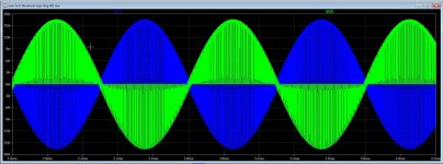
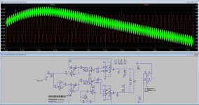
I have done a lot tryouts on class D also three level, that looks very nice.
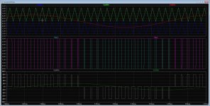
here sims with very low distortions, but three leven signals I do not see, but it does push pull I get no shoot through here, but I presume it is needed in real work, can try later the IR2010 models and mosfets to see.
I use only prepost feedback and I use a triangle carrier, the feedback looks it do job very well. maybe worth to build it this way and see. Also the three level do double the carrier, 500 mhz is triangle here and 1 Mhz I do see on output. first pic is plus and minus current of above push pull half.
regards
I have done a lot tryouts on class D also three level, that looks very nice.
here sims with very low distortions, but three leven signals I do not see, but it does push pull I get no shoot through here, but I presume it is needed in real work, can try later the IR2010 models and mosfets to see.
I use only prepost feedback and I use a triangle carrier, the feedback looks it do job very well. maybe worth to build it this way and see. Also the three level do double the carrier, 500 mhz is triangle here and 1 Mhz I do see on output. first pic is plus and minus current of above push pull half.
regards
Attachments
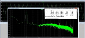
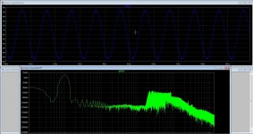
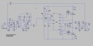
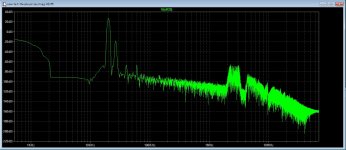
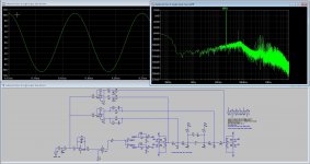
I have after some help managed to get PSRR sims, quite interesting how a supply do affect a class d amp, I still want to try a open loop first, and have a idea about lowering the PSRR in that design without using feedback, two opamps and i can probe the supply who do adjust the hysteric window such that PSRR get much much better however a hysteric window is not so lineair have I read.
Nice to see the IMD when I have a big ripple, if that is IMD because looks strange and single side only, it cancels out in H bridge, but still it is bad IMD distortion... quite important a good supply is.
here some sims with a supply added thanks to Mooly.
regards
Nice to see the IMD when I have a big ripple, if that is IMD because looks strange and single side only, it cancels out in H bridge, but still it is bad IMD distortion... quite important a good supply is.
here some sims with a supply added thanks to Mooly.
regards
Attachments
Last edited:
Good work.
There are 2 approaches to optimize PSRR in class D amplifiers.
1- The usage of as high open-loop gain as possible. This is mostly effective for LF, where integrators can provide huge amounts of gain. However, sound quality at mid-high frequencies can be tragic, if the circuit lacks a good PSRR to start with (from layout and modulation).
2- A self-oscillating modulator, fed from output filter, that, by definition, tracks instantaneous energy state of output filter, so in case the rail is dropping the cycle will be lengthening, and vice-versa. In this case rejection of ripple is only limited by the accuracy of the modulator and system (delay relative to Fsw period, cross-talk, ringing), not frequency dependent.
Good work.
There are 2 approaches to optimize PSRR in class D amplifiers.
1- The usage of as high open-loop gain as possible. This is mostly effective for LF, where integrators can provide huge amounts of gain. However, sound quality at mid-high frequencies can be tragic, if the circuit lacks a good PSRR to start with (from layout and modulation).
2- A self-oscillating modulator, fed from output filter, that, by definition, tracks instantaneous energy state of output filter, so in case the rail is dropping the cycle will be lengthening, and vice-versa. In this case rejection of ripple is only limited by the accuracy of the modulator and system (delay relative to Fsw period, cross-talk, ringing), not frequency dependent.
Hi Eva
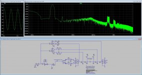
I have some Idea using a hysteric window who follow the supply ripple adjusting the following powerstage, can be done with two opamp (negative and positive error signal) between the audio and the comparator, what I did try the last time was making a openloop immuun for ripple coming from the supply, no succes yet, afcouse I can make a fast smps with very low ripple but the challence I do like so much is making a class d with normal supply and open loop, I have using 3 level output, that do not bad, but dispite I sim with the on the internet seen examples, ltspice do not let see 3 level signals, only full rail to rail squares but it is shiftet as expected, rule out dead time.
I have talk to some people who do not like feedback, and I see also good PSRR, just this is why I search so much for open loop and technology to get good audio, for low impedances, I do use 3 level who doubles the carrier so I can use a 100 Khz -3dB low pass who do, if I use mosfets with very low on resistance, give a quite low impedance, who maybe get worse when using a ripple driven window for comparator.
And maybe the idea of using the comparator for high PSRR is already used somewhere because I have never seen such much attemts to make a good class d amp on the internet and so much patents.
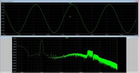
And see last picture has low distortion with only prepost feedback, First picture a big ripple who is not transferred to output. maybe combine with post CURRENT feedback is a idea, but as said, I do not like feedback, I have a hybrid who sounds so good that I still did not find a better one, except the all plate hybrid I have in wait stadium, hof the high end sails purpose. But class d do have mine interests.
regards
Attachments

Last edited:
There are several possible solutions for LF, including the ones you mention, but for HF there is only one, which is the general solution to the problem, the other are shortcuts.
"Genaral solution" to the problem does one analog convergence calculation for each half switching cycle (much like simulation software does digitally), it makes switching events converge with the time instants in which the energy deviation in output filter is balanced w.r.t. reference (Sigma Delta). Power supply ripple and output filter non-linearity and resonance are nulled in the calculation.
In some cases multiplicity of solutions exist, for example the benefits of class BD (3-level) are almost equivalent to those of a smart power supply that lowers rails at low signal.
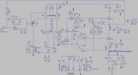
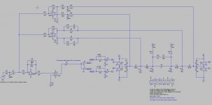
btw: I can't find the 3-level mechanism in posted schematic. This is 2-level, sawtooth modulator, two copies, with a lot of 2-pole gain on integrators, modest OL gain and distortion at high frequency. Be aware that in practice switching delay reduces the maximum amount of stable open-loop gain. Practical delay values are 100 to 200ns. In "simplified" models I recommend doing all simulations with 150ns delay to get realistic values.
"Genaral solution" to the problem does one analog convergence calculation for each half switching cycle (much like simulation software does digitally), it makes switching events converge with the time instants in which the energy deviation in output filter is balanced w.r.t. reference (Sigma Delta). Power supply ripple and output filter non-linearity and resonance are nulled in the calculation.
In some cases multiplicity of solutions exist, for example the benefits of class BD (3-level) are almost equivalent to those of a smart power supply that lowers rails at low signal.
btw: I can't find the 3-level mechanism in posted schematic. This is 2-level, sawtooth modulator, two copies, with a lot of 2-pole gain on integrators, modest OL gain and distortion at high frequency. Be aware that in practice switching delay reduces the maximum amount of stable open-loop gain. Practical delay values are 100 to 200ns. In "simplified" models I recommend doing all simulations with 150ns delay to get realistic values.
btw: I can't find the 3-level mechanism in posted schematic..
Just this is what I have trouble with, the comparator output is right for three level, using self oscillation, I get shifted suqares from comparators as needed but not the right switching.
the other with a sawtooth carrier also the same problem, not three level.
But
when using two opposite sawtoots level shifted it did work, however a lot of crossover, who can be solved by delay one side to get small pulses.
I did see in al the tests that there is need for high openloop, however strong feedbacks do like in normal amps give a dead clinical amplifier, as a uman in a prison, the problems that in high frequency parts the low pass is the cause and there are a lot of different solutions, there are good amps already out there, but at a cost, a lot of very complicated math and on the edge of stability, I cross mine hart when complete digital solution are coming, and if the result, a good sounding amp is possible, or we get a clinic sounding one like much class d does.
But it is fun, that I agree with. the multilevel is nice, moving distortion higher up and doubles carrier, there is need of multi sawtoots who are level shifted, because sawtoot is double sideband modulation inverting them has no effect but do ease the level shifting, however there is need for very fast opamps to keep things in line.
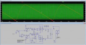
Thought of mine are bessel or bessel bandpass after that feedback and then a butterworth lowpas after, then sim like last pic. bessel keeps fase oke but less deep so need the extra butterworth, now only filtering away the ripple because bessel do demodulate, but have some loss on output signal.
Mine idea was also prepost feedback only or open loop and using air coils, oilcap parallelled with ceramic cap, on a 100 Khz -3dB setting, but then with 3 level or a carrier doubling technologie, 3 level has. I do like openloop because I have a hybrid I love.
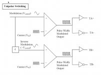
2th pic is such a 3 level comparator setting, however I have never get the power fets do the right thing with it, except with the double triangle that did work.
regards.
see pics.
Attachments
See attached paper. But that isn't class BD 3-level either. This is "dual phase". The advantage of using 2 phases (shifted 180deg) is approx. double bandwidth for same switching loss.
I mean that even companies that publish papers like that do not understand class D variants.
Class BD is something that puts little RMS voltage on output filter when it is idle, far less than 50% duty cycle. In practice that requires splitting the audio wave into upper and lower halves, dealing with enough idle ripple current on inductor considering it as bias (or handling DCM to CCM transition), and considering crossover distortion.
You may find information of interest in the following thread, this is digital class BD:
http://www.diyaudio.com/forums/clas...measurements.html?highlight=class+DB+inductor
Attachments
See attached paper. But that isn't class BD 3-level either. This is "dual phase". The advantage of using 2 phases (shifted 180deg) is approx. double bandwidth for same switching loss.
I mean that even companies that publish papers like that do not understand class D variants.
Class BD is something that puts little RMS voltage on output filter when it is idle, far less than 50% duty cycle. In practice that requires splitting the audio wave into upper and lower halves, dealing with enough idle ripple current on inductor considering it as bias (or handling DCM to CCM transition), and considering crossover distortion.
You may find information of interest in the following thread, this is digital class BD:
http://www.diyaudio.com/forums/clas...measurements.html?highlight=class+DB+inductor
Hi Eva
Only this did made 3 level, when I put multiple triangels I get even more levels upwards all the harmonics higher, but it is a challence I think.
For bias in uniform modulation small pulses can bu used as a bias, using dc os not good idea but hf pulses is. called bi-uniform modulation.
Strange was that I did not get 3 level with the single triangle and one normal 1 khz sinus and one inverted, but I did get the right signals from comparators so maybe mine ltspice switches has a problem.
The 3 level on picture did have a uge shoot through because the upper and lower switch are switching from 0 to rails exact the same time maing shorts, normal not seen on these, so mine bridge was wrong situated.
Thanks Eva for the papers and help.
kees
There is crown BCA too, the paper from 1998 is attached (released 20 years ago).
In order to find an orientation for your experimentation, to avoid running in circles, you have to figure out the purpose of each common topology, then decide.
- The purpose of class D is reduced loss at high power.
- The purpose of class BD is reduced loss at low signal.
- The purpose of BCA is to avoid the usage of MOSFET body diodes.
- The purpose of 2 phase class D is to double bandwidth.
- All low loss LC circuits, plus a switching delay, exhibit self-oscillation modes as long as closing some NFB loop is attempted.
- The purpose of triangle wave modulation, and pre-filter feedback, is to tolerate noisy signals for reducing PCB layout quality requirements. The triangle modulation takes over natural circuit oscillation and forces it to a certain frequency, as long as the triangle wave wins in amplitude.
- The original purpose of fixed frequency is to allow usage of LC filters in power supplies whose resonant frequencies would otherwise be excited by switching frequency.
- The 2nd purpose of fixed frequency is moving intermodulation artifacts to higher volume by phase-shifted synchronization.
- Variable frequency (saturation, hysteretic or phase shift) is not a shortcut, does not have a purpose, it is the natural way to operate switching converters, where timing calculation comes exclusively from the currents and voltages in the LC circuits, and input signal.
Thanks for your interest.
Attachments
Last edited:
- Home
- Amplifiers
- Class D
- Class D investigation.